
Xinjun Zhu, Ruiqun Sun, Linpeng Hou, Haichuan Zhao, Limei Song, Hongyi Wang. Single-Frequency Fringe Structured Light 3D Measurement Based on Regional Stereo Matching[J]. Laser & Optoelectronics Progress, 2024, 61(10): 1011006
- Laser & Optoelectronics Progress
- Vol. 61, Issue 10, 1011006 (2024)
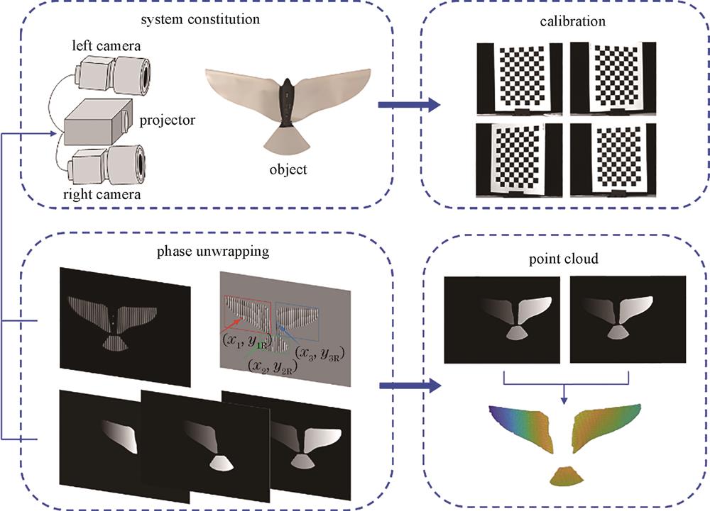
Fig. 1. Flow chart of the proposed scheme

Fig. 2. Fringe background separation. (a) Original left view image; (b) fringe information of left view; (c) background information of left view; (d) original right view image; (e) fringe information of right view; (f) background information of right view
Fig. 3. Phase segmentation. (a) Binary mask of right view; (b) phase division
Fig. 4. Local map of wrapped phase. (a) Wrapped phase of left view; (b) wrapped phase of right view
Fig. 5. Phase unwrapping initial point discrimination
Fig. 6. Regional phase unwrapping. (a)‒(c) Phase unwrapping process of left view; (d)‒(f) phase unwrapping process of right view
Fig. 7. Regional disparity matching. (a) Phase unwrapping of left view; (b) phase unwrapping of right view; (c) isolated object region partitioning; (d) disparity map of region 1; (e) disparity map of region 1 and region 2; (f) disparity map of the entire region
Fig. 8. Experimental setup diagram
Fig. 9. Multi-frequency heterodyne fringe patterns of a standard sphere. (a) Sinusoidal fringe patterns with a frequency of 16; (b) sinusoidal fringe patterns with a frequency of 18; (c) sinusoidal fringe patterns with a frequency of 21
Fig. 10. Wrapped phase. (a) (b) Four-step phase shift method; (c) (d) single-frame-based phase retrieval method
Fig. 11. Unwrapped phase. (a)(b) Unwrapped phase of multi-frequency heterodyne; (c)(d) unwrapped phase of four-step phase shifting; (e)(f) unwrapped phase of single-frame-based phase retrieval method
Fig. 12. Comparison of standard sphere point clouds. (a) Multi-frequency heterodyne; (b) four-step phase shifting; (c) single-frame-based phase retrieval method
Fig. 13. Original images of two sets of isolated objects. (a) Parallel placed isolated objects for left camera; (b) parallel placed isolated objects for right camera; (c) front and back placed isolated objects for left camera; (d) front and back placed isolated objects for right camera
Fig. 14. Experimental results of isolated objects. (a) (b) Unwrapped phase for left camera; (c) (d) unwrapped phase for right camera; (e) (f) wrapped phase for left camera; (g) (h) wrapped phase for right camera; (i) (j) reconstructed point clouds
Fig. 15. 3D reconstruction of dynamic object. (a)‒(d) Original images; (e)‒(h) wrapped phases; (i)‒(l) reconstructed point clouds
|
Table 1. Reconstruction accuracy of a standard sphere

Set citation alerts for the article
Please enter your email address
© Copyright 2018-2021 | Chinese Laser Press. All Rights Reserved 沪ICP备15018463号-20