
Sichen Zhang, Zhuo Li, Yanze Gao, Rui Shi, Jian Du, Qingfeng Shi, Xin Wang, Suhui Yang. Design of Optical System for Infrared Scene Projection in Cryogenic Environment[J]. Acta Optica Sinica, 2021, 41(14): 1422003
- Acta Optica Sinica
- Vol. 41, Issue 14, 1422003 (2021)
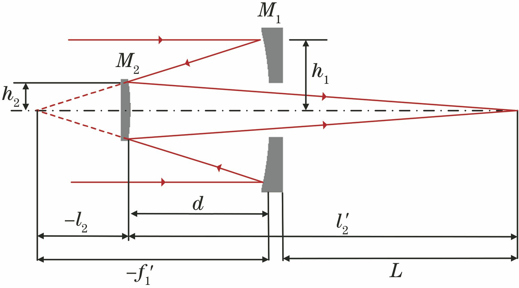
Fig. 1. Principle of the infrared image generation system. (a) Structure of the MEMS conversion film; (b) projection light path of the infrared image
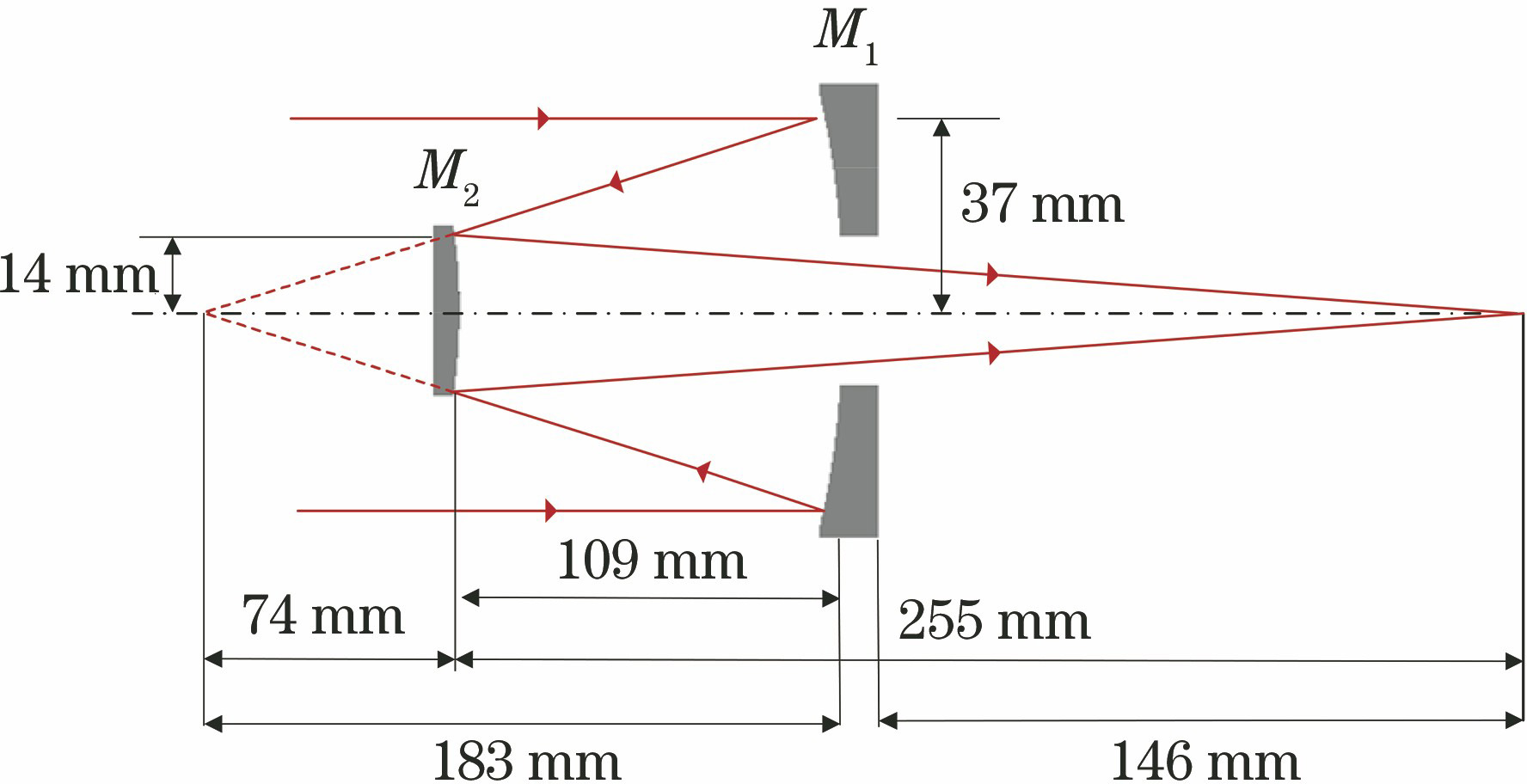
Fig. 2. Structure of the coaxial Cassegrain system
Fig. 3. Initial structure of the projection system
Fig. 4. Optimized structure of the projection system
Fig. 5. MTF curves of the projection system
Fig. 6. Energy diagram of the diffraction encircling circle of the projection system
Fig. 7. Installation of the primary mirror. (a) Clamping ring installation; (b) tablet installation
Fig. 8. Installation of the secondary mirror. (a) Clamping ring installation; (b) tablet installation
Fig. 9. Deformation analysis results of the primary mirror. (a) Clamping ring installation; (b) tablet installation
Fig. 10. Deformation analysis results of the secondary mirror. (a) Clamping ring installation; (b) tablet installation
Fig. 11. MTF of the system in 2 fixed modes
Fig. 12. Opto-mechanical structure of the projection system
Fig. 13. MTF of the system under different thermal expansion coefficients
Fig. 14. Optimization analysis flow chart of the projection system
Fig. 15. Change curve of the d with temperature
Fig. 16. MTF curves of the system at different temperatures. (a) 300 K; (b) 260 K; (c) 220 K; (d) 180 K; (e) 140 K; (f) 100 K
Fig. 17. MTF test device of the projection system
Fig. 18. Experimental results of the projection system. (a) Thermal image of the knife edge; (b) MTF curve
Fig. 19. Projection experimental setup at room temperature. (a) Experimental setup; (b) infrared image
Fig. 20. Projection experimental setup at low temperature. (a) Experimental setup; (b) infrared image
|
Table 1. Surface coefficients of the primary and secondary mirrors of the projection system
|
Table 2. Zernike coefficient of the primary mirror
|
Table 3. Zernike polynomial coefficients of the secondary mirror

Set citation alerts for the article
Please enter your email address
© Copyright 2018-2021 | Chinese Laser Press. All Rights Reserved 沪ICP备15018463号-20