• Chinese Optics Letters
  • Vol. 15, Issue 8, 081201 (2017)
Geng Wang1、2, Fei Xing1、2、*, Minsong Wei3, Ting Sun1、2, and Zheng You1、2
Author Affiliations
  • 1Department of Precision Instrument, Tsinghua University, Beijing 100084, China
  • 2State Key Laboratory of Precision Measurement Technology and Instruments, Tsinghua University, Beijing 100084, China
  • 3Department of Mechanical Engineering, University of California, Berkeley, CA 94720, USA
  • show less
    DOI: 10.3788/COL201715.081201 Cite this Article Set citation alerts
    Geng Wang, Fei Xing, Minsong Wei, Ting Sun, Zheng You. Optimization method for star tracker orientation in the sun-pointing mode[J]. Chinese Optics Letters, 2017, 15(8): 081201 Copy Citation Text show less
    Attitude sphere model of the sunlight based on the body coordinate system of the satellite.
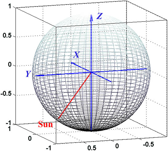
    Fig. 1. Attitude sphere model of the sunlight based on the body coordinate system of the satellite.
    Model of the earthlight for the sun-synchronous orbit satellite.
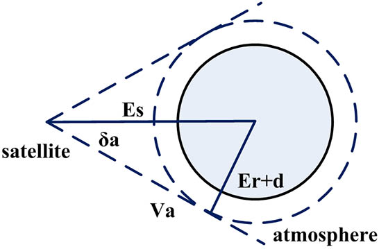
    Fig. 2. Model of the earthlight for the sun-synchronous orbit satellite.
    (a) Nadir-pointing and (b) sun-pointing mode of the satellite.
    Fig. 3. (a) Nadir-pointing and (b) sun-pointing mode of the satellite.
    Sunlight vector in the body coordinate system of the satellite.
    Fig. 4. Sunlight vector in the body coordinate system of the satellite.
    (Color online) Earth–satellite vector area in the body coordinate system of the satellite, (a) three-dimensional (3D) view, (b) Z axis view.
    Fig. 5. (Color online) Earth–satellite vector area in the body coordinate system of the satellite, (a) three-dimensional (3D) view, (b) Z axis view.
    Boundary curves of the Earth–satellite vector area.
    Fig. 6. Boundary curves of the Earth–satellite vector area.
    Boundary curves of the earthlight in the Z axis view.
    Fig. 7. Boundary curves of the earthlight in the Z axis view.
    Boundary curves of the Earth–satellite vector area.
    Fig. 8. Boundary curves of the Earth–satellite vector area.
    Installation orientation of the star tracker.
    Fig. 9. Installation orientation of the star tracker.
    Angle between star tracker orientation and the Earth–satellite vector for one year.
    Fig. 10. Angle between star tracker orientation and the Earth–satellite vector for one year.
    CharacteristicsAngle range
    X_minX_max17.0791°–162.9209°
    Y_minY_max62.9930°–117.0135°
    Z_minZ_max0°–180°
    Table 1. Maximum and Minimum Angles Between the Coordinate Axes and the Earth–satellite Vector Area
     XYZ
    Angle between the star tracker orientation and axis of the coordinate system112°22°90°
    Table 2. Installation Orientation of the Star Tracker in Sun-pointing Mode
    Geng Wang, Fei Xing, Minsong Wei, Ting Sun, Zheng You. Optimization method for star tracker orientation in the sun-pointing mode[J]. Chinese Optics Letters, 2017, 15(8): 081201
    Download Citation