• Laser & Optoelectronics Progress
  • Vol. 55, Issue 12, 121103 (2018)
Xin Li**, Ming Gao*, and Bin Feng
Author Affiliations
  • School of Optoelectronic Engineering, Xi'an Technological University, Xi'an, Shaanxi 710021, China
  • show less
    DOI: 10.3788/LOP55.121103 Cite this Article Set citation alerts
    Xin Li, Ming Gao, Bin Feng. Method for Target-Background Contrast Enhancement Based on Color Polarization Imaging[J]. Laser & Optoelectronics Progress, 2018, 55(12): 121103 Copy Citation Text show less
    Index of refraction of water and degree of polarization versus wavelength. (a) Index of refraction; (b) degree of polarization
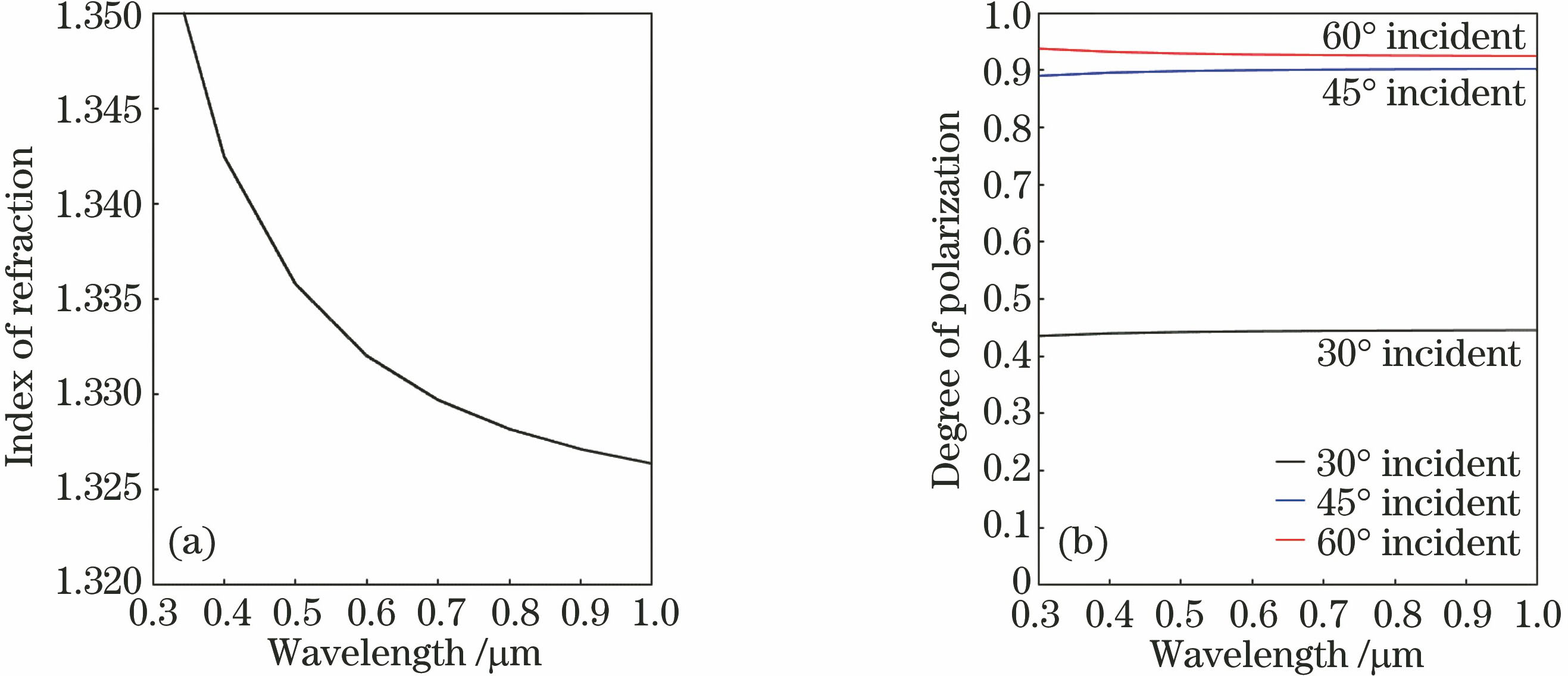
    Fig. 1. Index of refraction of water and degree of polarization versus wavelength. (a) Index of refraction; (b) degree of polarization
    Index of refraction of SiO2 and degree of polarization versus wavelength. (a) Index of refraction; (b) degree of polarization
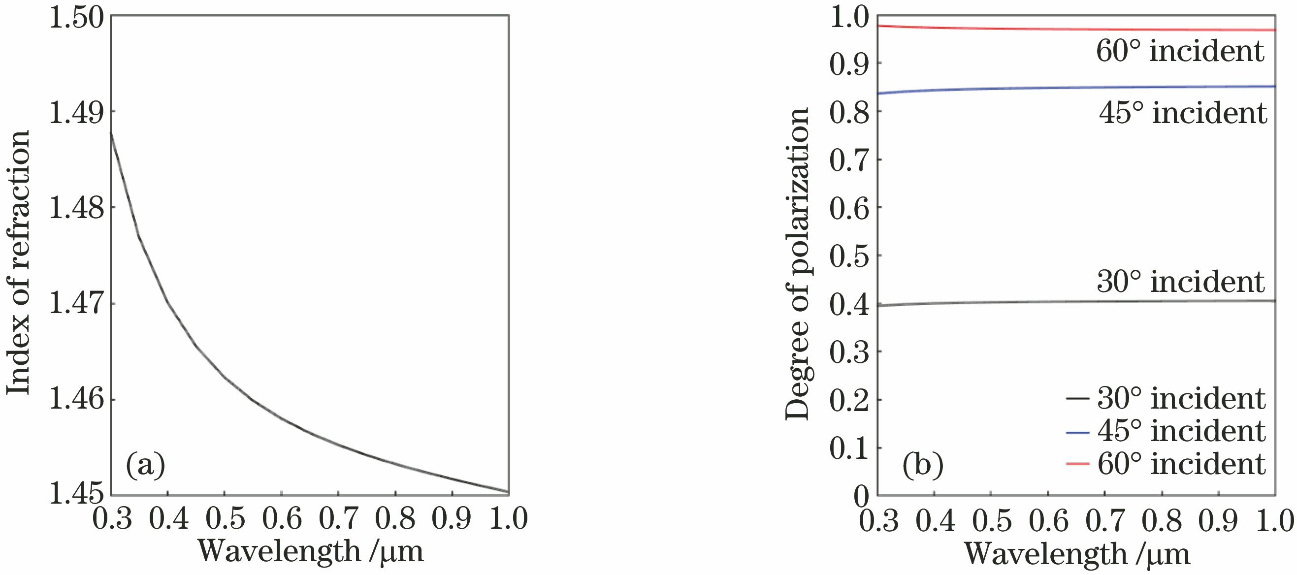
    Fig. 2. Index of refraction of SiO2 and degree of polarization versus wavelength. (a) Index of refraction; (b) degree of polarization
    Flow chart of polarization image processing
    Fig. 3. Flow chart of polarization image processing
    Experimental setup
    Fig. 4. Experimental setup
    Polarization images collected in experimental 1. (a) I0; (b) I45; (c) I90; (d) I135
    Fig. 5. Polarization images collected in experimental 1. (a) I0; (b) I45; (c) I90; (d) I135
    Polarization images within different channels in experiment 1. (a) R; (b) G; (c) B
    Fig. 6. Polarization images within different channels in experiment 1. (a) R; (b) G; (c) B
    Images obtained in experiment 1. (a) Original color image; (b) synthesized color polarization image; (c) color polarization image with threshold of 0.2
    Fig. 7. Images obtained in experiment 1. (a) Original color image; (b) synthesized color polarization image; (c) color polarization image with threshold of 0.2
    Polarization images collected in experimental 2. (a) I0; (b) I45; (c) I90; (d) I135
    Fig. 8. Polarization images collected in experimental 2. (a) I0; (b) I45; (c) I90; (d) I135
    Polarization images within different channels in experiment 2. (a) R; (b) G ; (c) B
    Fig. 9. Polarization images within different channels in experiment 2. (a) R; (b) G ; (c) B
    Images obtained in experiment 2. (a) Original color image; (b) synthesized color polarization image; (c) color polarization image with threshold of 0.2
    Fig. 10. Images obtained in experiment 2. (a) Original color image; (b) synthesized color polarization image; (c) color polarization image with threshold of 0.2
    SerialnumberImagecharacteristicTarget [R G B]Background [R G B]Vector-angledistanceC
    1Raw color image[0.2429 0.3581 0.1842][0.1836 0.2719 0.1409]0.00230.1369
    Color polarization image[0.1289 0.1178 0.1397][0.0643 0.0620 0.0923]0.07540.2779
    2Raw color image[0.6081 0.5895 0.5726][0.6909 0.6581 0.6144]0.05170.0187
    Color polarization image[0.1677 0.0985 0.0665][0.0424 0.0369 0.0487]0.44450.2448
    3Raw color image[0.1552 0.1313 0.5708][0.1892 0.1312 0.4782]0.09430.0869
    Color polarization image[0.1072 0.1764 0.0040][0.1574 0.1960 0.0049]0.11020.1596
    4Raw color image[0.5361 0.5341 0.4619][0.5762 0.5697 0.5329]0.04570.0200
    Color polarization image[0.1477 0.1578 0.2312][0.1561 0.1912 0.3408]0.05540.1510
    5Raw color image[0.4857 0.4973 0.5134][0.4275 0.3849 0.4139]0.09920.0314
    Color polarization image[0.1602 0.1452 0.1710][0.2571 0.2565 0.3321]0.27930.0472
    Table 1. Vector-angle distance and contrast between original and polarization images for each group of experiments
    Xin Li, Ming Gao, Bin Feng. Method for Target-Background Contrast Enhancement Based on Color Polarization Imaging[J]. Laser & Optoelectronics Progress, 2018, 55(12): 121103
    Download Citation