
Simin Li, Rong Cong, Xiaoxiao Yao, Jing Feng, Zhenzhou Tang, Shilong Pan. Chip-based microwave photonic frequency mixer (Invited)[J]. Infrared and Laser Engineering, 2021, 50(7): 20211056
- Infrared and Laser Engineering
- Vol. 50, Issue 7, 20211056 (2021)
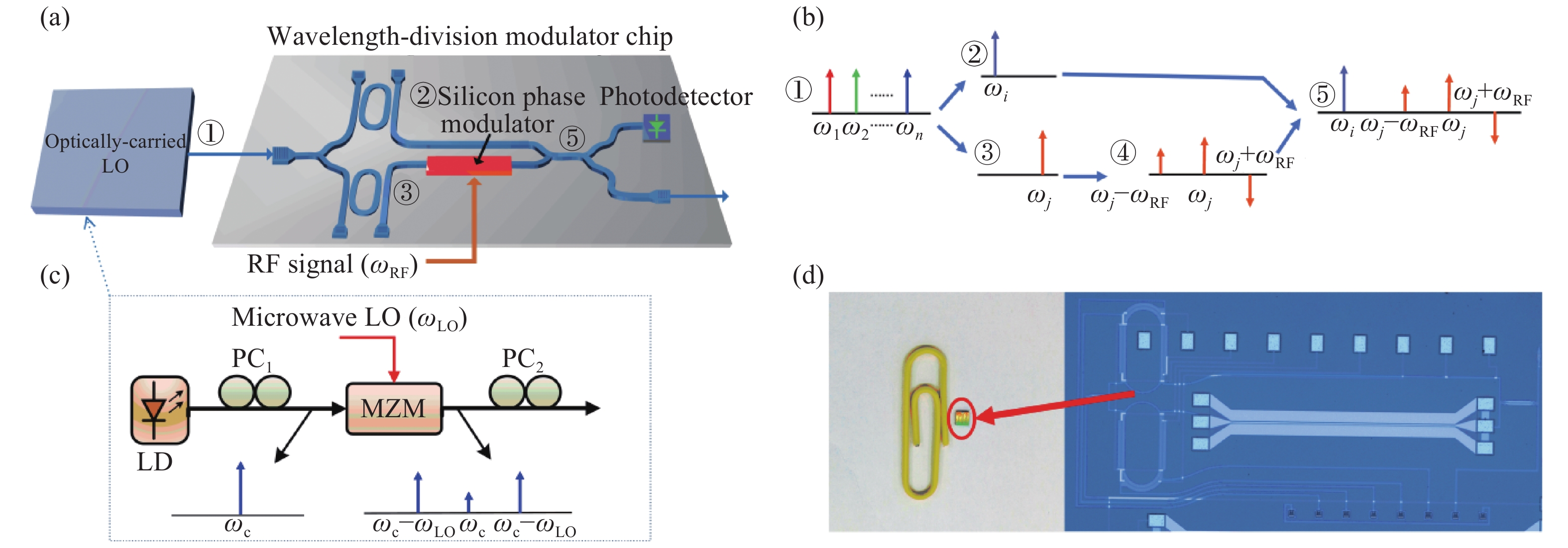
Fig. 1. (a) Schematic diagram of the proposed microwave photonic frequency mixer; (b) Optical signal at the main point of the system; (c) Optically-carried local oscillator used in the experiment; (d) Photographs of the wavelength-division modulator chip
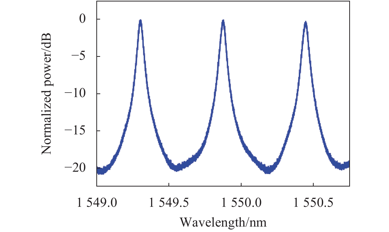
Fig. 2. Transmission response of the micro-ring filter
Fig. 3. Measured optical spectra of optical signal. (a) Coupled in the chip; (b) Coupled output from the chip
Fig. 4. Measured electrical spectra of system output. (a) ω RF=14 GHz (in a large frequency range); (b) RF frequency tuned in a frequency range from 6 to 16 GHz
Fig. 5. Simulated frequency spectra when the rejection ratio of the micro-ring filter is (a) 10 dB and (b) 40 dB; (c) Power of 2ω LO−ω RF and ω RF, and the spurs suppression ratio for the different rejection ratio of the micro-ring filter
Fig. 6. Simulated frequency spectra with (a) the maximum mixing spurs ω RF and (b) the minimum mixing spurs ω RF; (c) The spurs suppression ratio vs. the phase value of the optical phase shifter

Set citation alerts for the article
Please enter your email address
© Copyright 2018-2021 | Chinese Laser Press. All Rights Reserved 沪ICP备15018463号-20