
Zhijuan Shen, Haifeng Lin, Yiqing Cao. Design of Zoom Lens System with Movable Components Including Large Aperture and with Ultra-Wide Field of View[J]. Laser & Optoelectronics Progress, 2021, 58(7): 0708001
- Laser & Optoelectronics Progress
- Vol. 58, Issue 7, 0708001 (2021)
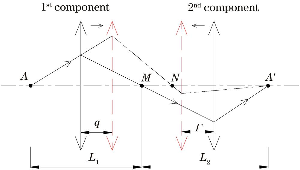
Fig. 1. Schematic of zoom motion compensation
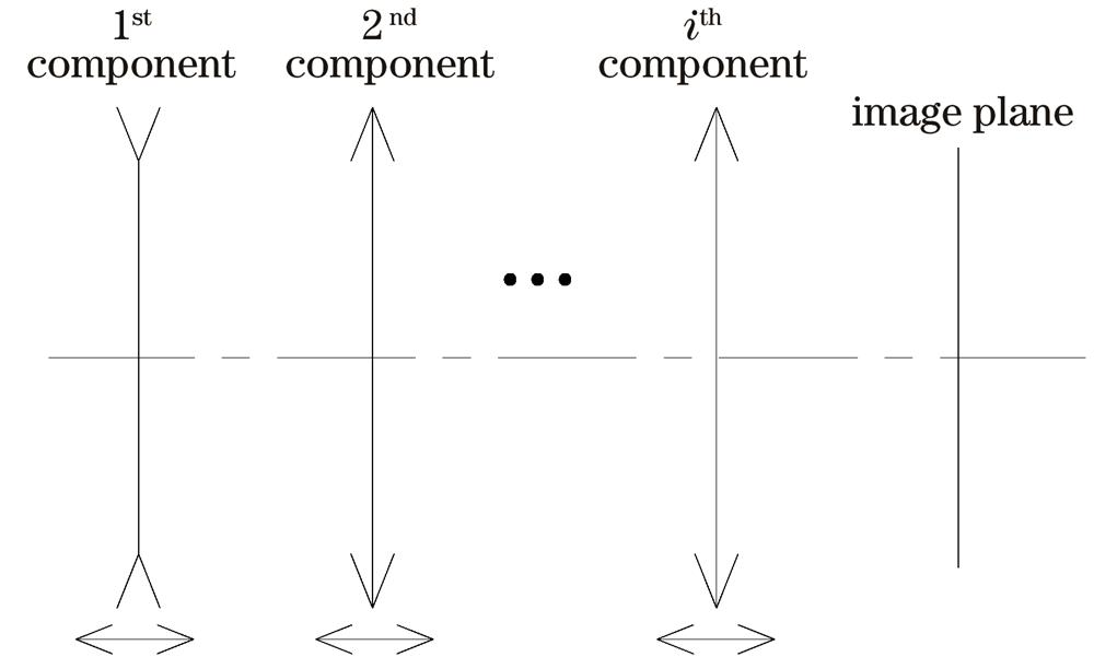
Fig. 2. Schematic of zoom motion of all-motion zoom optical system
Fig. 3. Schematic of component division in zoom optical imaging system
Fig. 4. Structure and optical path of optimized zoom optical system at different focal lengths. (a) f=6.54 mm; (b) f=11.77 mm; (c) f=17.00 mm
Fig. 5. MTF curves of optimized zoom optical system at different focal lengths. (a) f=6.54 mm; (b) f=11.77 mm; (c) f=17.00 mm
Fig. 6. Field curvature and F-theta distortion curves of optimized zoom optical system at different focal lengths. (a) f=6.54 mm; (b) f=11.77 mm; (c) f=17.00 mm
Fig. 7. Relative illumination of optimized zoom optical system at different focal lengths. (a) f=6.54 mm; (b) f=11.77 mm; (c) f=17.00 mm
|
Table 1. Main technical parameters of zoom optical system with ultra-wide field of view
|
Table 2. Main structural parameters of each state in optimized zoom optical system
|
Table 3. Optical parameters of optimized zoom optical system
| |||||||||||||||||||||||
Table 4. RMS radii of dot plot corresponding to field angles at different focal lengths

Set citation alerts for the article
Please enter your email address
© Copyright 2018-2021 | Chinese Laser Press. All Rights Reserved 沪ICP备15018463号-20