
Xiangjie Jia, Pengfei Hao, Min Li, Xiaoyan Wen, Haifei Lu. Resonance Modes and Influencing Factors of Micro Sensing Unit on Fiber End Face[J]. Acta Optica Sinica, 2022, 42(2): 0206005
- Acta Optica Sinica
- Vol. 42, Issue 2, 0206005 (2022)
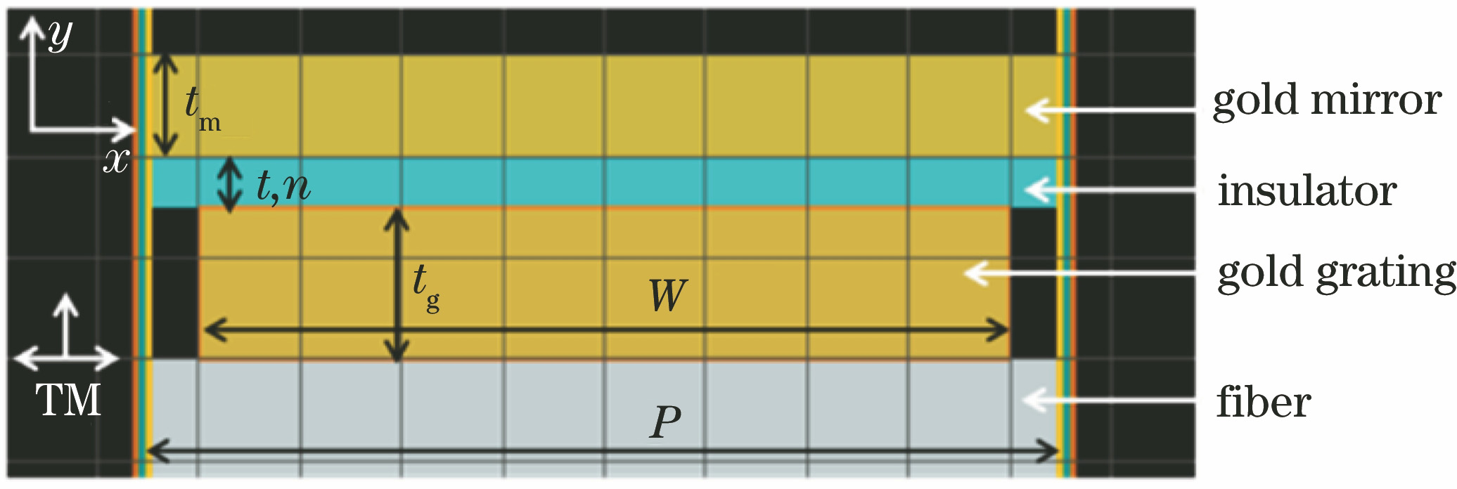
Fig. 1. Two-dimensional simulation model of gold grating-insulator-gold film
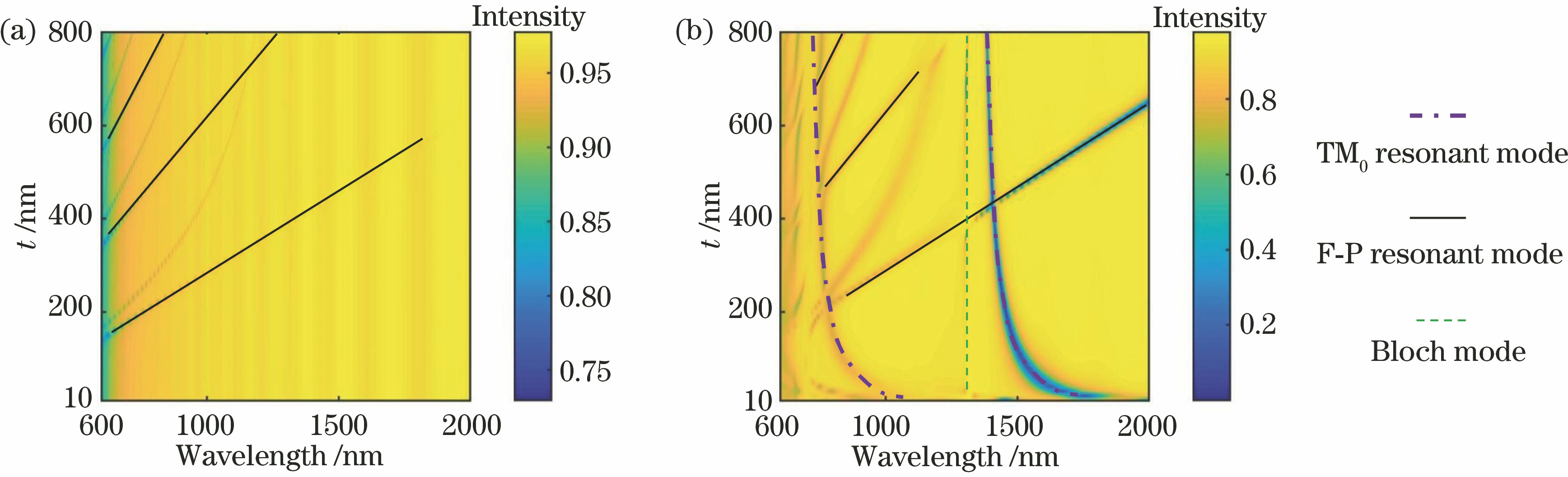
Fig. 2. Reflection spectra of resonator under different incident light. (a) TE light incident; (b) TM light incidence
Fig. 3. Reflection spectra of TM light incident at different dielectric layer thicknesses. (a) 30 nm; (b) 600 nm
Fig. 4. Distribution of Y-direction electric field components under different resonance modes. (a) 1st order TM0 resonance mode, λ=1671.69 nm; (b) 2nd order TM0 resonance mode, λ=985.84 nm; (c) 3rd order TM0 resonance mode, λ=795.22 nm; (d) Bloch surface mode, λ=1300.38 nm
Fig. 5. Distribution of X-direction electric field component in case of F-P resonance mode with TM light incident and t=600 nm. (a) 1st order F-P resonance mode, λ=1868.91 nm; (b) 2nd order F-P resonance mode, λ=957.16 nm
Fig. 6. Resonance diagram of TM0 mode
Fig. 7. Symmetric metal-coated dielectric waveguide model
Fig. 8. Performance of MIM structure with cavity length t=70 nm. (a) Reflection spectrum chromatics at different grating widths W; (b) variation curve of effective refractive index of TM0 resonant mode with wavelength
Fig. 9. Performance of MIM structure under different refractive index of intermediate dielectric layer. (a) Reflection spectrum chromatics; (b) variation curve of effective refractive index of TM0 resonant mode with wavelength
Fig. 10. Reflection spectrum chromatics and Y-direction electric field component at resonant wavelength under different grating thicknesses tg. (a) Reflection spectrum chromatics under different grating thicknesses tg; (b) tg=20 nm, Y-direction electric field component at resonance wavelength; (c) tg=200 nm, Y-direction electric field component at resonance wavelength
Fig. 11. Reflection spectrum and Y-direction electric field component at resonant wavelength under different grating periods P. (a) Reflection spectrum chromatics under different grating periods P; (b) P=900 nm, Y-direction electric field component at resonance wavelength; (c) P=1200 nm, Y-direction electric field component at resonance wavelength
Fig. 12. Reflection spectrum chromatics and Y-direction electric field component at resonant wavelength under different gold film reflector thicknesses tm. (a) Reflection spectrum chromatics under different gold film reflector thicknesses tm; (b) tm=20 nm, Y-direction electric field component at resonance wavelength; (c) tm=200 nm, Y-direction electric field component at resonance wavelength
Fig. 13. Performance curves of resonant wavelength and effective refractive index of nano-resonator under different conditions. (a) After refractive index of medium in cavity is fixed, resonant wavelength of nano-resonator varies with length of the cavity; (b) refractive index n of medium in cavity is 1.4, and effective refractive index of nano-resonator with different cavity lengths; (c) after cavity length is fixed, resonant wavelength of nano-resonator varies with refractive index; (d) cavity length t=50 nm, effective refractive index of nano-resonator under different refractive index
Fig. 14. SEM images under different magnification of fiber end grating . (a) 2000×; (b) 10000×
Fig. 15. Assembly system diagram and F-P resonant interference spectrum. (a) Five-dimensional displacement control platform, CCDs in horizontal and vertical planes; (b) optical fiber clamp and gold mirror platform; (c) position relative position of optical fiber and gold mirror observed by CCD; (d) F-P resonant interference spectra at different distances
Fig. 16. Assembly flowchart of optical fiber end nano-resonant structure
| |||||||||||||||||||||||||||||||||||
Table 1. Response sensitivity of nano-resonator to cavity length variation with fixed refractive index of medium in cavity
| |||||||||||||||||
Table 2. Response sensitivity of resonator with different cavity length to refractive index change of medium in cavity

Set citation alerts for the article
Please enter your email address
© Copyright 2018-2021 | Chinese Laser Press. All Rights Reserved 沪ICP备15018463号-20