Light is a precious resource that nature has given to human beings. Converting green, recyclable light energy into the mechanical energy of a micromotor is undoubtedly an exciting challenge. However, the performance of current light-induced micromotor devices is unsatisfactory, as the light-to-work conversion efficiency is only . In this paper, we propose and demonstrate a laser-induced rotary micromotor operated by -type photopheresis in pure liquid glycerol, whose energy conversion ratio reaches as high as , which is 3–6 orders of magnitude higher than that of previous light-induced micromotor devices. In addition, we operate the micromotor neither with a light field carrying angular momentum nor with a rotor with a special rotating symmetrical shape. We just employ an annular-core fiber to configure a conical-shaped light field and select a piece of graphite sheet (with an irregular shape) as the micro-rotor. The -type photophoretic force introduced by the conical-shaped light field drives the rotation of the graphite sheet. We achieve a rotation rate up to 818.2 r/min, which can be controlled by tuning the incident laser power. This optical rotary micromotor is available for twisting macromolecules or generating vortex and shear force in a medium at the nanoscale.
1. INTRODUCTION
Light is a precious resource that nature has given to human beings. It is undoubtedly an exciting challenge to force light to rotate an object as a rotary motor. Besides trapping force [1,2], light radiation pressure can also exert torque on an object through the angular momentum transfer [3,4], and the torque originates from two basic principles: 1) the angular momentum may be carried by the light source itself, including circularly polarized beams [5,6], elliptically polarized beams [7,8], Laguerre–Gaussian beams [9,10], and helical beams [11,12] and 2) the trapping light itself does not carry angular momentum; the torque originates from light scattering on an object with a helical shape, including the helix [13,14], sprinkler [15], and propeller [16,17] shapes. The momentum change during deflection exerts a torque on the trapped object. It seems that it is necessary to configure a special light source with angular momentum or fabricate a special object with a helical shape to create a light-induced rotary micromotor.
In addition, the momentum flow of a laser with a power is in general ( is light speed with the value of ), which leads to a very inefficient conversion of optical power into mechanical work. Suppose that, due to optical angular momentum transfer, light can expect the torque () on a micro-rotor in the order of [pN·μm], which achieves a rotation angular frequency () of the micro-rotor of 1 Hz with an incident laser power () of 1 mW. Therefore, the light-to-work conversion ratio can be estimated as [14], which is in the order of and is unsatisfactory. A more efficient strategy for the light-to-work conversion is provided by optothermal effects [18,19]. In this paper, we propose and demonstrate a light-induced rotation of a piece of graphite sheet (GS) in liquid glycerol based on the -type photopheresis [20,21], which originates from the optothermal effects. In our previous studies, -type photophoretic force can trap [21] and drive the vibration [20] of an absorbing particle. The -type photophoretic force, which is larger than the radiation pressure [22], may drive a micro-rotor to rotate as a micromotor in a liquid circumstance. Being different from the light-induced rotation introduced by the radiation pressure, we perform the rotation of a piece of GS without a special helical shape by using a conical-shaped light field without angular momentum. The light-to-work conversion ratio of our light-induced rotation is , which is 3–6 orders of magnitude higher than the radiation pressure. The rotation rate can be real-time controlled by tuning the incident light power, and we achieve a rotation rate up to 818.2 r/min (see Fig. 1 and Visualization 1). Compared with the light-induced rotation introduced by radiation pressure, the advantages of the proposed light-induced rotation include: 1) the light-to-work conversion ratio is 3–6 orders of magnitude higher and the rotation is achieved via a simple method; 2) one does not need to build a special light field with angular momentum or fabricate the rotor to be a special shape. Our results can provide real-time monitoring and control of light-driven rotation by all-fiber devices, and they thus take a significant step toward the integration of such systems into lab-on-a-chip devices, performing as rotational probes or as light-driven micropumps.
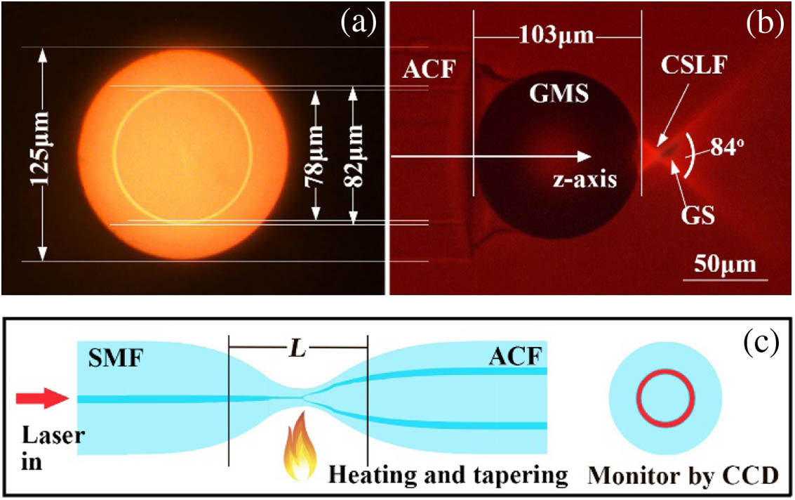
Figure 1.(a) Profile image of the ACF; (b) image of the ACF probe made of a section of ACF and a GMS; (c) schematic diagram of heating and tapering the SMF and ACF.
We configure the fiber probe with a section of annular-core fiber (ACF) and a glass microsphere (GMS) doped with and BaO. The output light field from the fiber probe is conical shaped, and we name it a conical-shaped light field [CSLF; see Fig. 1(b)]. The vertex angle of the CSLF is 84°. We employ a piece of GS as the rotor, which will lay on the sidewall of the CSLF when it falls into the effective area of the CSLF. The GS will rotate about the fiber probe main axis ( axis) as a rotor. The cladding diameter of the ACF is 125 μm [see Fig. 1(a)]. The outer diameter of the annular core is 82 μm, and the inner diameter is 78 μm. The refractive index of the annular core is 1.4681, and the refractive index of the cladding is 1.4632.
Sign up for Photonics Research TOC. Get the latest issue of Photonics Research delivered right to you!Sign up now
We launch the laser power into the core of the ACF via the fiber heating and tapering method [23], which includes the following steps. 1) We fuse a single-mode fiber (SMF) and the ACF with a fiber fusion splicer (Fujikura, FSM-100). Almost no scattering light can be seen from the annular core monitored by the CCD camera. 2) We heat and draw the fusion point gradually to form a tapered zone [see Fig. 1(c)]. The direct-coupling power is near zero when the drawing length () is smaller than 13 mm. This is because the diameter of the annular core is relatively large; the annular core is far from the core of the SMF at first, and the radius of the mode fields is too small. 3) When the drawing length is larger than 13 mm, light power is gradually transferred from the SMF into the ACF. As the annular core is close enough to satisfy the weak-coupling condition, there are fluctuations in the annular core due to circumferential power transfer therein. 4) When the power distribution in the annular core is even, we stop heating and tapering when the drawing length is about 22 mm, and only a small part of the optical power is lost to leakage. Most of the input optical power has been coupled from the SMF into the ACF. The insertion loss can be defined as the power in the annular core divided by the total input power, and the minimum value of the insertion loss is around 1 dB. 5) Finally, we package the fibers to cover the tapered area.
We achieve the ACF probe by sticking a GMS on the tip of the ACF. The diameter of the GMS is 103 μm, and the refractive index of the GMS is 2.2. We stick the ACF and the GMS with the ultraviolet curable adhesive, and the detailed preparation process can be found in the Ref. [24]. The steps are as follows. 1) We employ two three-axis high-precision positioners to align the center of the GMS and the ACF, which are monitored by two NA 0.55 optical microscopes. 2) We insert the end of the ACF into the liquid ultraviolet curing glue (Apollo UV, JiGA) and then pick it up to form a liquid droplet. 3) Due to the surface tension of the liquid glue, the GMS is lifted up and makes a point contact with the ACF when we move the ACF near the GMS. 4) Based on the gravity of the GMS and the surface tension of the glue, the GMS is aligned to the center of the ACF. 5) Finally, we obtain the integrated composite body of the GMS and ACF cured by ultraviolet light.
B. Rotation Driving Principle
When we launch a beam of the laser into the ACF probe, a CSLF will be generated near the GMS [see Fig. 2(a)]. The laser energy will be absorbed by the liquid glycerol, and a thermal field will be generated near the GMS [see Fig. 2(b)]. When a piece of GS falls into the CSLF, it will be attracted and trapped near the cross point () of the CSLF [see Fig. 2(c)]. However, due to the shape of the GS, whose length () and width () are much larger than the thickness (), the GS will not remain horizontal, and it will “fall” on the sidewall of the CSLF [see Figs. 1(b) and 2(c)]. In order to describe the position and direction of the GS, we built a coordinate system (). Precisely, the ε axis is along the sidewall of the CSLF. The -type photophoretic force () will be generated and exerted on the GS along the -axis and -axis directions. We suppose that is the photophoretic force along the axis and is the photophoretic force along the axis.
Figure 2.(a) Schematic diagram of the CSLF introduced by the ACF probe. (b) Schematic diagram of the thermal field introduced by the CSLF. The axis is the fiber probe main axis. (c) Schematic diagram of the GS trapped by the light-induced thermal field. The long axis of the GS is along the sidewall of the CSLF. (d) Schematic diagram of the net force exerted on the GS.
For stable trapping and rotation around the -axis direction, the -axis component of the -type photophoretic force must balance the -axis component of at the equilibrium position . The -axis components of and will provide the torque and centripetal force for the rotation motion around the -axis direction. We decompose both forces along the axis and axis, respectively [see Fig. 2(d)], and obtain the forces of , and . When , the net force along the axis is zero, and the GS will attain equilibrium on the position [see Fig. 2(d)]. Along the -axis direction, the net force is , which provides the centripetal force for the rotation, driving the GS to rotate around the axis.
3. RESULTS AND DISCUSSION
A. Simulation and Calculation
Figure 3.(a) Simulated results of the light field distribution near the fiber probe; the diameter of the focus spot is 2.6 μm; (b) simulated results of the thermal field distribution near the fiber probe; (c) the schematic diagram shows the calculation of the photophoretic force along the axis; (d) the schematic diagram shows the calculation of the photophoretic force along the axis.
Based on the commercial COMSOL Multiphysics simulation software, we obtain the light field and temperature field distribution near the GS, including the initial temperature of the liquid , the temperature of the liquid layer around the rotor , and the temperature of the rotor surface . Thus, we may calculate , the thermal accommodation coefficients of the GS on the left side of the axis [see Fig. 3(c)], and , the thermal accommodation coefficients of the GS on the right side of the axis. We divide the edge of the GS into pieces, calculate the thermal accommodation coefficients and of each point, and then sum them: and . Then we may calculate the net , , and the net , which represents the net photophoretic force () exerted on the GS along the axis direction. Similarly, we may obtain the net -type photophoretic force () along the -axis direction. Finally, we decompose both forces ( and ) along the axis and axis, respectively [see Fig. 2(d)]. We calculate the expressions of and [ is seen in Fig. 2(b)] with different position coordinates (). When μ (μ) and μ (μ), the calculated results of are equal to those of , which means the GS will be trapped on the position of (5.1 μm, μ) and then perform the rotation around the axis.
B. Rotation Rate and Power
Figure 4.Relationship between the rotation rate of the GS and the incident laser power with the and probes. Here E.R. means the experimental results and F.R. means the fitting results.
We calculate the rotation rate in the unit of revolutions per minute (r/min). When the incident laser power is 3.2 mW, the rotation rate of the GS is r/min. When the incident laser power is 14.9 mW, the spinning rate of the GS reaches r/min. When the incident laser power is smaller than 3.2 mW, the fiber probe cannot achieve the rotation of the GS. When the incident laser power is larger than 14.9 mW, the temperature near the GS will be too high to trap the GS in a stable state. The GS will be adhered to and move towards the tip of the fiber probe, losing the rotation motion.
C. Efficiency of Laser-to-Work Conversion
Owing to the micrometer scales, the resistance of the GS rotation is dominated by the viscosity of the liquid glycerol. That is, the rotation-induced flow in the liquid glycerol has very small Reynolds numbers [20] and can be accurately modeled in the Stokes limit (creeping flow). We provide the dynamic equation of the movement of the GS as which involves rotation () of the GS in the trap and the viscous friction () from the surrounding liquid glycerol. can be expressed as , is the moment of inertia of the GS around the rotatory main axis ( axis), and is the angular acceleration.
At microscopic scales, the viscous drag from the liquid glycerol exerted on the GS is linearly related to the GS’ angular velocity (rotation rate ). As such, the torque can be written as [14], where is the damping ratio, the expression of which depends on the shape of the object and is given by the Stokes law.
Equation (1) is a first-order differential equation. The transient evolution of the rotation rate is given by the following solution:
In the practical experiment, the stationary solution corresponds to and is therefore given by .
The drag from the liquid glycerol on the GS is linearly related to the object’s angular velocity. As such, the power dissipation from the rotation can be written as [14]
We can estimate the efficiency of the laser-to-work conversion as the ratio between the optical power and the mechanical power that is required to spin the GS at the same speed by an external torque. The maximum observed speed is r/min. for a corresponding incident power on the GS of . Therefore, the laser-to-work conversion efficiency is where , which depends on the geometry of the GS [25], is the viscous coefficient of the liquid glycerol, μ is the width of the GS, and μ is the length of the GS. Both and are measured from the experimental results. The calculated result of the power conversion efficiency is , which is 3–6 orders of magnitude higher than that of the radiation pressure-induced rotation.
D. Effects of the Vertex Angle of CSLF
Figure 5.(a) Image of the probe; (b) image of the probe with some parameters; (c) image of the probe performing the rotation of a piece of GS; (d) image of the probe; (e) image of the probe with some parameters; (f) image of the probe performing the rotation of a piece of GS.
We provide the comparison results in Fig. 4. For the rotation introduced by the probe, when the incident laser power is 1.8 mW, the rotation rate of the GS reaches . When the incident laser power is 13.5 mW, the spinning speed of the GS reaches . When the incident laser power is smaller than 1.8 mW, the fiber probe cannot perform the rotation. When the incident laser power is larger than 13.5 mW, the temperature near the GS will be too high to trap the GS in a stable state; the GS will be adhered to and move towards the tip of the fiber probe, losing the rotation function. The comparison results of the rotation introduced by the two fiber probes indicate that the vertex angle of the CSLF affects the relationship between the rotation rate and the incident laser power. The larger the vertex angle, the larger the maximum rotation rate.
4. CONCLUSION
In conclusion, we describe and demonstrate a laser-induced rotary micromotor operated by -type photopheresis in pure liquid glycerol. The micromotor converts laser energy directly to mechanical energy, and the laser-to-work conversion ratio is , which is 3–6 orders of magnitude higher than that of the other light-induced micromotors. The -type photophoretic force drives the rotation of the GS. With the incident laser power of 14.9 mW, the maximum rotation rate reaches 818.2 r/min. This optical spin micromotor is available for twisting macromolecules or generating vortex and shear force in a medium at the nanoscale with the help of a microlens [26], which is convenient for practical applications in biology, medicine, and metamaterials fields.
Acknowledgment
Acknowledgment. We thank the College of Physics and Optoelectronic Engineering of Harbin Engineering University for providing technique support under the supervision of the Key Laboratory of In-fiber Integrated Optics, Ministry of Education.