
Ci Yin, Shiyao Fu, Yahui Zhang, Yanwang Zhai, Heng Zhou, Chunqing Gao. Beam combination at any angles with a multilayer grating[J]. Chinese Optics Letters, 2018, 16(8): 080502
- Chinese Optics Letters
- Vol. 16, Issue 8, 080502 (2018)
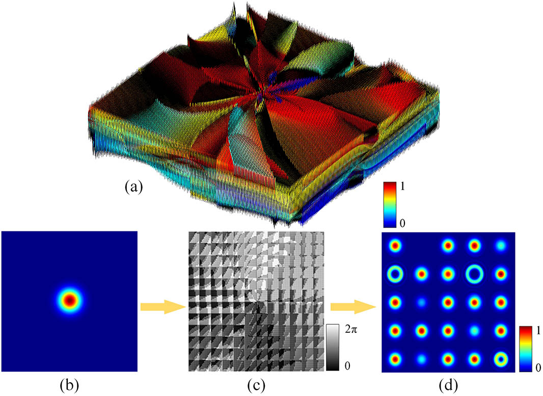
Fig. 1. Gratings designed to generate 5 × 5 I l 5 × 5 ( − 2 , 1 ) l = 2 ( 1 , 1 ) l = 3 ( 2 , − 2 ) l = 1 ( 2 , 2 ) I = 0.5 ( 1 , − 1 ) I = 0.5 ( − 1 , − 2 ) I = 0.4 ( − 1 , 0 ) I = 0.3 ( − 1 , 2 )
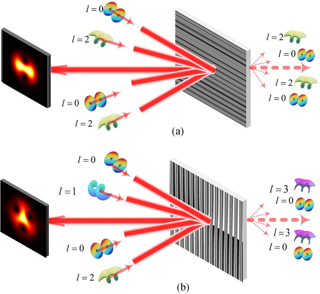
Fig. 2. Schematic of beam combination at any angles with a continuous grating. (a) Beam combination diagram. (b) Changing topological charges and combining beams at the same time.
Fig. 3. System of beam combination. LD—laser diode; L1—convex lens; PBS1, PBS2, PBS3—polarization beam splitter; SLM—liquid-crystal spatial light modulator; HWP—half-wave plate; QWP1, QWP2—quarter-wave plate; QP—q-plate; M—reflective mirror; AS—aperture stop, and CCD—CCD camera.
Fig. 4. Column (a) and column (b) are the Gaussian beams and OAM beams before the beam combination, respectively. Column (c) is the interference patterns after the beam combination.
Fig. 5. Experimental results when the grating constant is changed in proportion with the diffraction orders. The grating constants corresponding to (a), (b), (c), and (d) are, respectively, T = 20 λ 80 λ 140 λ 200 λ
Fig. 6. Columns (a) and (b) are the situations that change the position of the reflective mirror (incident angles). Column (c): combining beam and changing topological charge at the same time.

Set citation alerts for the article
Please enter your email address
© Copyright 2018-2021 | Chinese Laser Press. All Rights Reserved 沪ICP备15018463号-20