Ci Yin, Shiyao Fu, Yahui Zhang, Yanwang Zhai, Heng Zhou, Chunqing Gao. Beam combination at any angles with a multilayer grating[J]. Chinese Optics Letters, 2018, 16(8): 080502
Copy Citation Text
A scheme for beam combination at any angles employing a specially designed multilayer grating is proposed. Such a grating is able to convert noncoaxial laser beams to coaxial ones, and the combined beams are able to output along the normal line of the grating. The intensity and the phase structure of combined beams can also be controlled. The experiments are carried out by loading an encoded grating on a liquid-crystal spatial light modulator. The results agree well with the simulations. This method of beam combination with a multilayer grating serves to simplify the complexity of beam combination.
Beam combination plays an important role in scaling power and radiance with a high efficiency and good quality. Combiners are broadly classified as free space and guided wave ones. In free space, numerous wavelength (spectral) techniques and coherent (phased array) techniques have been proposed and demonstrated[1], including wavelength-division-multiplexing[2] or orbital angular momentum (OAM)[3] multiplexing for optical communications[4], polarizing optical elements for polarization beam combination[5,6], diffractive optical elements[7,8], volume Bragg gratings[9], and dispersive optical elements[10]. It is obvious that diffractive elements can meet the condition of high power as well as high channel count combination, of which the multiport and free-space nature are able to bring about a higher combination efficiency and power scaling than other approaches[11].
Among them, the Dammann grating has been widely used, as binary phase profiles are easy to fabricate. Examples of such beam combinations include aperture filling[12], quantum-cascade lasers[13], nonseparable phase-controlled Dammann gratings[14], and so on. OAM multiplexing in optical communications can also be considered as a kind of beam combination. By exploiting Dammann gratings, significant progress has been achieved in free-space OAM-based communication[15]. However, acting as a beam splitter, a Dammann grating splits an input beam into multiple output beams with symmetrical distribution on both sides of zero-order diffraction. So, the beam combination is limited to the reciprocal process of grating splitting, that is, Dammann gratings can only realize beam combination of symmetrical incident beams, but not the beams at any angles. In addition, the input beams have to be incident at a given diffraction order, or the combination efficiency will drop drastically[16]. In order to match the splitting angles, the input angles need to be adjusted precisely instead of setting the incident angles at random, which brings great difficulties to experiment setups[17,18].
In this Letter, we theoretically and experimentally demonstrate a specially designed grating[19,20] for beam combination at any angles. Compared with binary phase gratings, multilevel phase gratings or continuous phase gratings[21] present a higher combination efficiency[13]. The parameters of our multilevel gratings are determined according to the incident angles. Since the incident lasers are free from aiming at diffraction orders, the complexity of the optical experiments is simplified and the flexibility is improved. Moreover, the proportion of intensity and phase distribution of combined beams can also be controlled by continuous gratings.
Sign up for Chinese Optics Letters TOC. Get the latest issue of Chinese Optics Letters delivered right to you!Sign up now
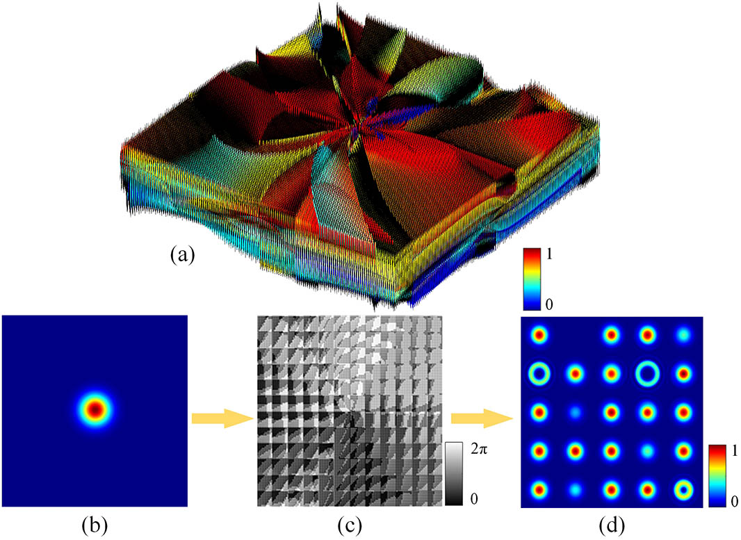
The splitting effect of the multilevel diffraction grating is shown in Fig. 1. This grating is designed to produce a one-dimensional array or two-dimensional rectangular arrays with corresponding diffraction orders. The intensity of each diffraction order can be unequal. Such beams can also carry helical phases with different topological charges[22].
Figure 1.Gratings designed to generate beams with different normalized intensities () and topological charges () with corresponding diffraction orders. (a) Schematic of a continuous grating structure. (b) Simulated Gaussian beams. (c) The computed phase profile. (d) Far-field diffraction patterns when Gaussian beams propagate through (c): , , , , , , , a missing order.
When designing a certain two-dimensional grating, we can set the parameters of amplitude and phase at each diffraction order, and then accumulate them. The phase transmission function can be Fourier expanded[23,24] as where , are the diffraction orders in the and direction, respectively. , refer to the angular frequency, which can be written as with , the grating constants in the , direction, respectively. is a normalization coefficient. Generally, the transmittance function is complex, and the product of the transmittance function and its conjugate is a constant according to the pure phase grating condition
It is clear that the equation can only be established if the diffraction order is (, ). Therefore, for the array grating designed by this method, the desired array cannot be generated by phase-only modulation. There are uncorrelated diffraction orders, which makes the energy distribution of each diffraction order in the array not in accordance with the theoretical value. So, it is necessary to optimize the grating by the GS algorithm[25], and so on. The degree of optimization of the transmittance function is expressed by the normalized coefficient . The Fourier coefficient denotes the complex amplitude of the beam at diffraction orders , where is azimuthal angle, and , , represent amplitude, initial phase, and topological charge in the diffraction order (, ), respectively.
Figure 1 shows the diffraction pattern generated by this continuous grating. In some diffraction orders, the intensity and phase are modulated, respectively, to some degree. Meanwhile, the missing order can be controlled. According to the reciprocal process of grating splitting, such gratings can be used to combine the lasers of different intensity and convert OAM states with high efficiency.
First, we introduce the principle of combining beams at any angles. Selecting the horizontal direction of the incident beams, the incident angles are , with corresponding diffraction orders separately. Then the transmission function is
Supposing that the grating constant is fixed, under the condition of equal wavelengths, different levels of the grating equation can be written as:
Therefore, there is a certain proportional relationship between the diffraction orders and the incident angles:
It is worth noting that the diffraction order does not have to be an integer here, implying that beams can be combined at any angles, as shown in Fig. 2.
Figure 2.Schematic of beam combination at any angles with a continuous grating. (a) Beam combination diagram. (b) Changing topological charges and combining beams at the same time.
In order to distinguish coaxial and noncoaxial interference phenomena clearly, we use a Gaussian beam to interfere with an OAM beam. The noncoaxial interference of Gaussian beams and OAM beams will generate fork shapes[26], while coaxial interference will appear as petals. Here, the OAM beam is generated through a q-plate. The q-plate is a polarization-modulating device made of a nematic liquid crystal that can achieve the exchange of the laser beams from the spin angular momentum to the orbital angular momentum[27]. By controlling the uneven distribution of the main axis of liquid-crystal molecules on the cross section, a local half-wave plate is formed at every point on the cross section. Meanwhile, the geometric helical phase is introduced into the modulated beam, contributing to the OAM beams output. The topological charge of the generated OAM beams is 2 in this experiment.
We start with a Gaussian beam emitted from a 1.6 μm laser diode (LD). The polarization axis of the beam outputs from the first polarization beam splitter is rotated by a half-wave plate, thus the PBS1 and HWP are used together to adjust the laser intensities. The second polarization beam splitter separates the beam into horizontal (H) and vertical (V) polarization components. The H component is directed onto the liquid crystal spatial light modulator (SLM) while the V component goes through a q-plate with an order and then transfers as an H component by QWP2 and PBS3. When a Gaussian beam at 1550 nm passes through a q-plate (), a second-order OAM beam will be generated.
By finding the coordinates of the center of the SLM (Holoeye, PLUTO-TELCO-013-C, nominal resolution pixel, pixel pitch 8.0 μm), we ensure that the two beams hit the same point. Modulation is realized by loading the phase on the liquid crystal SLM. The SLM we apply here is a phase-only modulator with the modulation efficiency of 80%.
The optical experimental system is shown in Fig. 3. The distance between the LD and the SLM is 116.5 cm, the horizontal distance between the laser and its reflected beam is 31.5 cm, and the distance between the LD and reflected beam is 87.0 cm. So, the incident angle of the H components can be calculated by means of the cosine theorem and the semiangular formula of trigonometric functions; the input angle of the V components can be obtained by the same method. The simulated and experimental results are shown in Fig. 4. First, under the same incident angle, we change the grating constant from to . Figure 5 shows that the change of the grating constant has no effect on the experiment results, and the key point is to keep the corresponding proportion same. This verifies our theoretical analysis that the beam combination is only related to the setting of the diffraction order and is independent on the grating constant. To verify the arbitrariness of the experiment, we change the relative position between the prism and mirrors, and the expected results can still be obtained by grating combination at new angles [Figs. 6(a) and 6(b)], which indicates that even if the angle of incidence is changed the combination of beams at any angles can be achieved. Figure 6(c) presents the experimental results of changing the topological charge of incident beams and simultaneously combining beams. The results agree well with the simulations.
Figure 4.Column (a) and column (b) are the Gaussian beams and OAM beams before the beam combination, respectively. Column (c) is the interference patterns after the beam combination.
Figure 5.Experimental results when the grating constant is changed in proportion with the diffraction orders. The grating constants corresponding to (a), (b), (c), and (d) are, respectively, , , , and .
Figure 6.Columns (a) and (b) are the situations that change the position of the reflective mirror (incident angles). Column (c): combining beam and changing topological charge at the same time.
The key point of the experiment is to measure the distance between the various optical elements accurately to calculate the accurate incident angles and set the parameters of the grating according to the incident angles to achieve beam combination. In addition, the incident beams need to be aligned with the center of the grating, and the two beams should coincide perfectly. This can be achieved by adjusting the central coordinates of the SLM.
The output power of the combined beams is measured as 3.223 mW. The incident Gaussian beam is measured as 10.44 mW, while the OAM beam is measured as 12.17 mW. The main cause of low efficiency is the modulator. Power loss can be attributed to the following reasons. First, the SLM we apply is a phase-only modulator with a modulation efficiency of 80%, which means 20% of the input beams are not modulated and lost. Then, the ideal beam splitting efficiency is 81.06%[19]. Without the control phase by coherent beam combining technology, the ideal combination efficiency is half of the splitter. In addition, the diffraction effects of other diffraction orders could lead to power loss. The optical elements also result in intensity attenuation. Our research focuses more on geometric beam combination, which aims to verify whether the specially designed gratings will make input beams geometrically overlap under the condition of arbitrary incident angles. With the help of phase control technology, this method can obtain a higher combination efficiency, thus realizing more practical applications. With the development of material processing technology, more efficient modulation devices[28,29] will be produced and greatly improve the efficiency of the beam combination in the future.
In summary, a scheme for beam combination at any angles is presented. The principle is demonstrated by using a specially designed continuous grating. The proposed scheme can convert beams from noncoaxial laser beams to coaxial ones, controlling the intensity and the phase structure at the same time. An experiment is performed, and verifies the feasibility of the proposed concept. The theoretical and experimental results provide an important basis for simplifying the complexity of experimental setups.
Ci Yin, Shiyao Fu, Yahui Zhang, Yanwang Zhai, Heng Zhou, Chunqing Gao. Beam combination at any angles with a multilayer grating[J]. Chinese Optics Letters, 2018, 16(8): 080502