• Acta Optica Sinica
  • Vol. 40, Issue 10, 1006001 (2020)
Zhuangzhuang Xue1、2, Li Pei1、2、*, Yuheng Xie1、2, Dan Hao1、2, and Ke Zhu1、2
Author Affiliations
  • 1Key Laboratory of All Optical Network and Advanced Telecommunication Network, Ministry of Education, Beijing Jiaotong University, Beijing 100044, China
  • 2Institute of Lightwave Technology, Beijing Jiaotong University, Beijing 100044, China
  • show less
    DOI: 10.3788/AOS202040.1006001 Cite this Article Set citation alerts
    Zhuangzhuang Xue, Li Pei, Yuheng Xie, Dan Hao, Ke Zhu. Filterless 24-Tupling Frequency Millimeter-Wave Generator[J]. Acta Optica Sinica, 2020, 40(10): 1006001 Copy Citation Text show less
    Schematic diagram of the proposed mm-wave signal generator
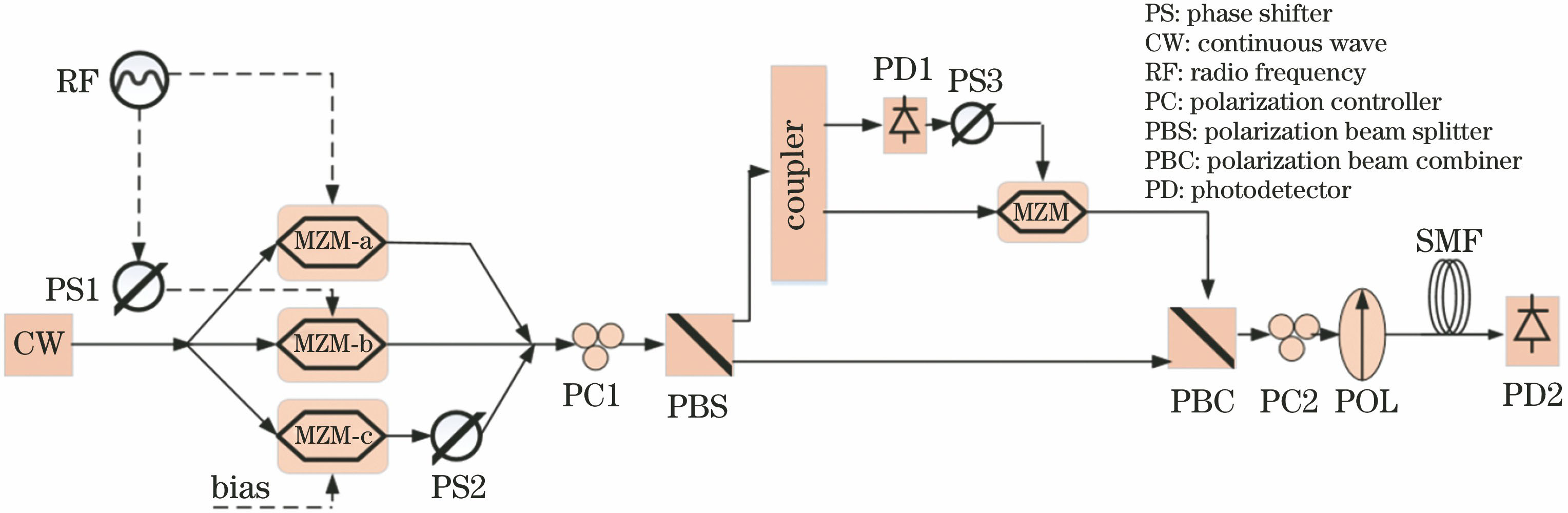
    Fig. 1. Schematic diagram of the proposed mm-wave signal generator
    Spectrum of the output optical signal from the structure of triple-parallel Mach-Zehnder modulator
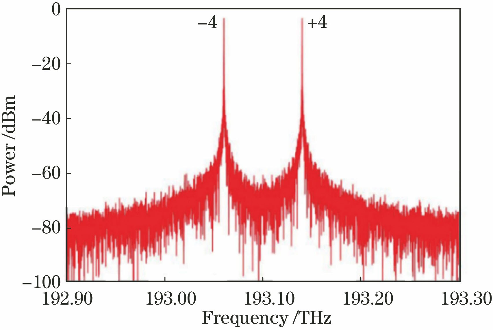
    Fig. 2. Spectrum of the output optical signal from the structure of triple-parallel Mach-Zehnder modulator
    Output results. (a) Optical spectrum; (b) RF spectrum
    Fig. 3. Output results. (a) Optical spectrum; (b) RF spectrum
    OSSR and RFSSR versus modulation depth. (a) Scheme of this article; (b) scheme of Ref. [20]
    Fig. 4. OSSR and RFSSR versus modulation depth. (a) Scheme of this article; (b) scheme of Ref. [20]
    Maximum value of Q and maximum value of BER versus fiber transmission distance. (a) maximum value of Q; (b) Maximum value of BER
    Fig. 5. Maximum value of Q and maximum value of BER versus fiber transmission distance. (a) maximum value of Q; (b) Maximum value of BER
    OSSR and RFSSR versus extinction radio. (a) OSSR; (b) RFSSR
    Fig. 6. OSSR and RFSSR versus extinction radio. (a) OSSR; (b) RFSSR
    OSSR and RFSSR versus bias voltage of MZM-c
    Fig. 7. OSSR and RFSSR versus bias voltage of MZM-c
    OSSR and RFSSR versus offset of driving signals between MZM-a and MZM-b
    Fig. 8. OSSR and RFSSR versus offset of driving signals between MZM-a and MZM-b
    Eye diagram versus linewidth of laser. (a) δ=5 MHz; (b) δ=15 MHz; (c) δ=35 MHz; (d) δ=50 MHz
    Fig. 9. Eye diagram versus linewidth of laser. (a) δ=5 MHz; (b) δ=15 MHz; (c) δ=35 MHz; (d) δ=50 MHz
    BER versus linewidth of laser
    Fig. 10. BER versus linewidth of laser
    ParameterValue
    Optical power of CW laser /dBm30
    Center frequency of CW laser /THz193.1
    Linewidth of CW laser /MHz10
    Dispersion of optical fiber /(ps·nm-1·km-1)17
    Half-wave voltage of all MZM modulators /V4
    Frequency of RF signal /GHz10
    Table 1. System parameters
    Zhuangzhuang Xue, Li Pei, Yuheng Xie, Dan Hao, Ke Zhu. Filterless 24-Tupling Frequency Millimeter-Wave Generator[J]. Acta Optica Sinica, 2020, 40(10): 1006001
    Download Citation