Chawin Sitawarin, Weiliang Jin, Zin Lin, Alejandro W. Rodriguez, "Inverse-designed photonic fibers and metasurfaces for nonlinear frequency conversion [Invited]," Photonics Res. 6, B82 (2018)

Search by keywords or author
- Photonics Research
- Vol. 6, Issue 5, B82 (2018)

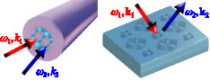
Fig. 1. Schematic illustration of third-harmonic generation and second-harmonic generation processes in inverse-designed microstructured fibers and metasurfaces, respectively.

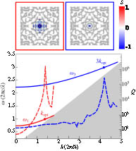
Fig. 2. Dispersion relations (solid line) and radiative lifetimes Q (dashed line) versus propagation wavenumber k of TM 01 fundamental ω 1 (red) and third-harmonic ω 3 (blue) modes in a chalcogenide/PES fiber optimized to achieve frequency matching ω 3 = 3 ω 1 and large nonlinear overlaps at k opt = 1.4 ( 2 π / λ ) . The shaded area in gray indicates regions lying below the chalcogenide light cone. The top insets show the fiber cross section overlaid with corresponding power densities at ω 1 (left) and ω 3 (right).
![Nonlinear overlap factor |β3|2 corresponding to fundamental and third-harmonic modes in fibers that have been optimized to ensure phase-matched modes (k3=3kopt) at various fundamental-mode propagation wavenumbers kopt, for both TE01 (blue) and TM01 (red) polarizations, by the application of either topology (circles or squares) or shape (triangles) optimization. The gray-shaded area denotes the regime of guided modes below the chalcogenide lightline. For comparison, also shown is |β3|2 (black cross) of a standard plain fiber manually designed for operation at ω1=0.914(2πc/λ) and k1=0.992(2π/λ) [77]. Shown as insets are fiber cross sections along with power densities of fundamental modes optimized at four different kopt={0.1,1.4,1.7,2.0}(2π/λ) for both TE01 (upper insets) and TM01 (lower insets), with (i)–(iii) obtained via topology optimization and (iv) via shape optimization.](/Images/icon/loading.gif)
Fig. 3. Nonlinear overlap factor | β 3 | 2 corresponding to fundamental and third-harmonic modes in fibers that have been optimized to ensure phase-matched modes (k 3 = 3 k opt ) at various fundamental-mode propagation wavenumbers k opt , for both TE 01 (blue) and TM 01 (red) polarizations, by the application of either topology (circles or squares) or shape (triangles) optimization. The gray-shaded area denotes the regime of guided modes below the chalcogenide lightline. For comparison, also shown is | β 3 | 2 (black cross) of a standard plain fiber manually designed for operation at ω 1 = 0.914 ( 2 π c / λ ) and k 1 = 0.992 ( 2 π / λ ) [77]. Shown as insets are fiber cross sections along with power densities of fundamental modes optimized at four different k opt = { 0.1 , 1.4 , 1.7 , 2.0 } ( 2 π / λ ) for both TE 01 (upper insets) and TM 01 (lower insets), with (i)–(iii) obtained via topology optimization and (iv) via shape optimization.

Fig. 4. (a) Schematic illustration of second-harmonic generation in a square-lattice metasurface of finite thickness t and period Λ × Λ . Shown to the right are dielectric profiles and mode profiles | E | 2 corresponding to two inverse-designed metasurfaces, both over single unit cells and z = 0 cross sections. The structures are optimized to ensure frequency and phase matching for light incident at (i) an angle θ = 3 ° or (ii) normal incidence. Dark (white) represents gallium phosphide (vacuum) regions. (b) Convergence of the objective function with respect to iteration number, leading to structure (ii).
|
Table 1. Representative Second-Harmonic Generation FOMs for Both Hand- and Inverse-Designed Metasurfaces, Including χ ( 2 ) , Fundamental Wavelength λ 1 , and Conversion Efficiency η per Unit Cella

Set citation alerts for the article
Please enter your email address