• Journal of Infrared and Millimeter Waves
  • Vol. 41, Issue 2, 506 (2022)
Yuan CEN, Jian-lan XIE, and Jian-jun LIU*
Author Affiliations
  • Key Laboratory for Micro/Nano Optoelectronic Devices of Ministry of Education & Hunan Provincial Key Laboratory of Low-Dimensional Structural Physics and Devices,School of Physics and Electronics,Hunan University,Changsha 410082,China
  • show less
    DOI: 10.11972/j.issn.1001-9014.2022.02.018 Cite this Article
    Yuan CEN, Jian-lan XIE, Jian-jun LIU. A photonic crystal flat lens insensitive to polarization mode and light source[J]. Journal of Infrared and Millimeter Waves, 2022, 41(2): 506 Copy Citation Text show less
    The model of two-dimensional(2D)triangular lattice PC flat lens with scatterer-size gradient:The red arrow represents the light path of plane wave focusing,and the black arrow represents the light path of point source imaging
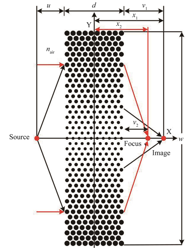
    Fig. 1. The model of two-dimensional(2D)triangular lattice PC flat lens with scatterer-size gradient:The red arrow represents the light path of plane wave focusing,and the black arrow represents the light path of point source imaging
    (a)TM polarization band structure of common photonic crystal(CPC)with r=0.29µm(black),0.34µm(red)and 0.39µm(blue).(b)TE polarization band structure of CPC with r=0.29µm(black),0.39µm(red)and 0.49µm(blue). Dot dash line,dot line and solid line represent the first,second and third bands respectively. The EFL of the second TM polarization band of CPC:(c)r=0.29µm,(d) r=0.34µm,(e) r=0.39µm. The EFL of TE polarization band of CPC:(f)r=0.39µm(the second band),(g) r=0.44 µm(the third band),(h)r=0.49µm(the third band).(i)The red,purple and black solid lines represent(c),(d)and(e)EFL corresponding to the incident light source frequency,respectively.(j)The purple and black solid lines represent(g)and(h)EFL corresponding to the incident light source frequency,respectively. Because(f)has no negative refraction,it is no longer studied separately. The blue dot line is EFL of light cone. The black arrow is an incident beam,incident from the air into the PC. The red arrow is the propagation direction of the beam in the PC,that is,the refracted beam.(i)and(j)are only schematic diagrams[35-36].
    Fig. 2. (a)TM polarization band structure of common photonic crystal(CPC)with r=0.29µm(black),0.34µm(red)and 0.39µm(blue).(b)TE polarization band structure of CPC with r=0.29µm(black),0.39µm(red)and 0.49µm(blue). Dot dash line,dot line and solid line represent the first,second and third bands respectively. The EFL of the second TM polarization band of CPC:(c)r=0.29µm,(d) r=0.34µm,(e) r=0.39µm. The EFL of TE polarization band of CPC:(f)r=0.39µm(the second band),(g) r=0.44 µm(the third band),(h)r=0.49µm(the third band).(i)The red,purple and black solid lines represent(c),(d)and(e)EFL corresponding to the incident light source frequency,respectively.(j)The purple and black solid lines represent(g)and(h)EFL corresponding to the incident light source frequency,respectively. Because(f)has no negative refraction,it is no longer studied separately. The blue dot line is EFL of light cone. The black arrow is an incident beam,incident from the air into the PC. The red arrow is the propagation direction of the beam in the PC,that is,the refracted beam.(i)and(j)are only schematic diagrams35-36.
    Take λ=3.303µm90.84 THz as an example. The field distribution of spherical wave stimulated by point source incident on the PC flat lens with scatterer-size gradient:(a)TM polarization mode.(b)TE polarization mode. The field distribution of plane wave incident on the PC flat lens with scatterer-size gradient:(c)TM polarization mode.(d)TE polarization mode. In TM and TE polarization modes,the field power of point source(PS)imaging and plane wave(PW)focusing:(e)axis plane(f)image plane and focal plane. STM and STE represent the field power of point source imaging in TM and TE polarization modes respectively. WTM and WTE represent the field power of plane wave focusing in TM and TE polarization modes respectively.
    Fig. 3. Take λ=3.303µm90.84 THz as an example. The field distribution of spherical wave stimulated by point source incident on the PC flat lens with scatterer-size gradient:(a)TM polarization mode.(b)TE polarization mode. The field distribution of plane wave incident on the PC flat lens with scatterer-size gradient:(c)TM polarization mode.(d)TE polarization mode. In TM and TE polarization modes,the field power of point source(PS)imaging and plane wave(PW)focusing:(e)axis plane(f)image plane and focal plane. STM and STE represent the field power of point source imaging in TM and TE polarization modes respectively. WTM and WTE represent the field power of plane wave focusing in TM and TE polarization modes respectively.
    Yuan CEN, Jian-lan XIE, Jian-jun LIU. A photonic crystal flat lens insensitive to polarization mode and light source[J]. Journal of Infrared and Millimeter Waves, 2022, 41(2): 506
    Download Citation