Joint International Research Laboratory of Information Display and Visualization, School of Electronic Science and Engineering, Southeast University, Nanjing 210096, China
Hao Zhang, Lei Yao, Yuyan Pang, Jun Xia, "Flexible and high-efficiency generation of arbitrary vector vortex beams on hybrid-order Poincaré sphere," Chin. Opt. Lett. 16, 092601 (2018)
Copy Citation Text
We propose theoretically and verify experimentally a compact optical configuration to directly generate arbitrary vector vortex beams on a hybrid-order Poincaré sphere with good flexibility and high efficiency based on a reflective phase-only liquid crystal spatial light modulator (LC-SLM). The conversion system, consisting of an LC-SLM and a quarter-wave plate, can be considered a flexible dielectric metasurface to simultaneously modulate inhomogeneous polarization and helical phase-front. This approach has some advantages, including a simple experimental setup, good flexibility, and high efficiency. Orthogonally polarized modes alignment and an explicit superposition existing in the conventional method are not necessary in the proposed method, which exhibits potential applications in many advanced domains.
The Poincaré sphere[1] is a prominent geometry for describing the polarization state of beams, and the sets of all polarization states are mapped to points on the surface of this theoretical framework. Nevertheless, this geometry is limited to the most fundamental homogeneous polarization as only linear, elliptical, and circular so that it is unable to describe the vector beam[2], known as possessing a spatially inhomogeneous polarization state. To overcome this limitation, the high-order Poincaré sphere (HOPS)[3] is indicated. The beams with spatially inhomogeneous polarized states, such as azimuthally and radially polarized beams, can be interpreted as a superposition of two orthogonal circular polarization states with opposite orbital angular momentums and are geometrically represented by a point on the surface of the HOPS[3]. However, such solutions are still limited to some special cases because the orbital angular momentums on the south and north poles are constrained to be opposite. Recently, the hybrid-order Poincaré sphere (HyOPS)[4] was developed to further break such a confine and extend the HOPS to a more general form. Unlike the previous HOPS, the orbital angular momentums on the HyOPS should not be confined to this certain condition and can be chosen arbitrarily.
Most recently, the more general vector vortex beam on HyOPS[4] has attracted a lot of attention due to both its spatially inhomogeneous polarization and helical phase-front, contributing to the application in many advanced optical schemes, such as beam focusing[5], particle acceleration[6], vector optical vortex filtering[7], photonic spin Hall effect[8,9], photon entanglement[10], and communication[11,12]. Compared with the single vortex beam and single vector beam, the vector vortex beam on HyOPS provides more degrees of freedom that can be used in beam manipulation[5,13,14]. Encouraged by these advantages, a great variety of impressive approaches to generate states on HyOPS has also been demonstrated experimentally, such as a plate[15–17], laser resonator configurations[18], interferometers[19], plasmonic metasurfaces[20,21], and a spatial light modulator (SLM)[22–25]. However, most of the above schemes have less flexibility, and the polarization converter, which processes polarization singularity, is usually fixed. Although flexible modulation can be realized by SLM, the complicated light path involving a grating or more than one SLM leads to low efficiency and high-precision alignment. Therefore, a flexible method to generate states on HyOPS with high efficiency as well as a compact optical configuration is still highly demanded.
In this Letter, we report a novel method to directly generate arbitrary vector vortex beams on HyOPS with a good flexibility and a high efficiency based on a reflective phase-only liquid crystal SLM (LC-SLM). As opposed to previous studies, orthogonally polarized modes alignment and an explicit superposition are not necessary, so the higher efficiency can be implemented. The conversion system, consisting of an LC-SLM and a quarter-wave plate (QWP), can be considered as a flexible dielectric metasurface to simultaneously modulate inhomogeneous polarization and helical phase-front and may find promising applications in many advanced domains. The experimental results match well with the theoretical derivation based on the Jones matrix calculation.
Sign up for Chinese Optics Letters TOC. Get the latest issue of Chinese Optics Letters delivered right to you!Sign up now
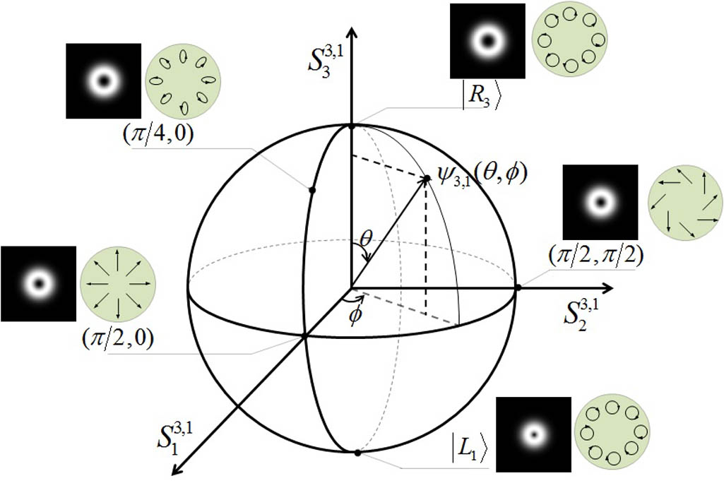
Figure 1 depicts one of the HyOPS with and . The north and south poles stand for the scalar right and left circular polarization with phase topological charges and , respectively. Here, the orthogonal circular polarization eigenstates are Laguerre–Gauss beams. Obviously, the point on the HyOPS is the combination of and with various coefficients, and the HyOPS can map the polarization and phase of arbitrary vector vortex beams on its surface. Through this geometrical representation, polarization and phase evolution of light within the interaction with media could become much clearer.
Figure 1.Schematic illustration of HyOPS with and . Only the main polarization distribution is marked.
Arbitrary vector vortex beams can be represented geometrically on HyOPS and algebraically described by the following equation in terms of the azimuth and polar angles in the sphere[4,26]: where and are the right and left circular polarizations, respectively. is the angle in the polar coordinate system. and are the normalization coefficients of the intensity of right and left circular polarization, respectively. Note that the field described by Eq. (1) can be transformed into ψwhere and are the topological charges related to the spatial distributions of phase and polarization, respectively.
A schematic of the experimental arrangement for generating arbitrary vector vortex beams on the HyOPS is shown in Fig. 2. The core of the experiment setup is the conversion system shown in Fig. 2, which is used to convert the arbitrary homogenous polarized light into the states on HyOPS. The Jones matrix is a universal tool for theoretical calculation to represent the function of the optical devices. A theoretical calibration method based on a Jones matrix is demonstrated in this Letter.
Figure 2.Schematic of experimental arrangement for generating arbitrary vector vortex beams on the HyOPS.
The laser source is a collimated expanded green laser beam with 532 nm wavelength and non-polarization. The exit light through the linear polarizer P1 can be described by the Jones matrix as where is the rotated angle of the polarizer along the horizontal direction. As is well known, the QWP will introduce a phase shift of between the vertical and horizontal directions. The function of the QWP can be described by the Jones matrix as[27]where is the angle between the fast axis of the QWP and the horizontal direction. In this system, we set QWP1 (Fig. 2) at 0°. So, the output light, passing through the QWP1, can be written as
For the conversion system shown in Fig. 2, QWP2 is placed in front of the reflective phase-only LC-SLM. The LC-SLM (Holoeye PLUTO) used here is a two-dimensional array of independently addressable uniaxial birefringent pixel pitches, which has a pixel size μμ and resolution of . The retardation for each LC-SLM pixel is characterized by an ordinary refractive index and an extraordinary refractive index , which can be voltage-controlled independently. For the LC-SLM used in our experiment, the horizontally polarized light is the extraordinary light. A computer-generated hologram (CGH) is loaded onto the LC-SLM to modulate the spatial phase distribution of the horizontal direction, while the vertical one will be simply reflected and unaffected. Therefore, the function of the LC-SLM in our experiment can be described by the multiplication of three Jones matrices as[27]where , , is the thickness of the liquid crystal cell, and is the wavenumber ( is the wavelength of the light), respectively. The fast axis of QWP2 in Fig. 2 is along 135° with respect to the horizontal direction. The incident light passes through QWP2 with the fast axis oriented at 135° and gets reflected off the SLM. Then, the reflected light goes through QWP2 again. However, due to the conversion of coordinates caused by the influence of the reflection, the fast axis of QWP2 rotates to 45° for the reflected light. Thus, the Jones matrix representation of the conversion system can be calculated as[24]where is the rotation matrix. It is obvious that the conversion system indicates an effective polarization rotation of at each pixel of the LC-SLM and an additional phase of , which is regarded as an unexpected phase in previous literature[24]. In this work, we truly make use of the additional phase and the polarization rotation by setting (where is an integer, and is the azimuth angle). Ignoring the constant term , Eq. (7) should have the following form:
From Eq. (8), it is obvious that the conversion system can simultaneously generate an inhomogeneous polarization and a helical phase-front.
According to Eqs. (3)–(8), the final output optical field through the conversion system in Fig. 2 can be written as with
By comparing with Eq. (2), it is obvious that the output optical field described by Eq. (9) stands for arbitrary vector vortex beams on HyOPS, where the topological charges related to the spatial distributions of phase and polarization are and . In addition, from Eq. (9), the relationship between the angles on HyOPS and the coefficient can be established: , . Therefore, we can change the coefficients , , and to generate arbitrary vector vortex beams on HyOPS.
The polarization states structure of the generated HyOPS beams is measured and recorded by using a polarizer and a charge-coupled device (CCD). We first set P1 at to generate the states on the equator of HyOPS, namely the vector vortex beams with linear polarization, such as azimuthally and radially polarized beams. The encoded holograms and the patterns observed by the CCD with or without a polarizer at different orientations are displayed in Fig. 3. The spatially varying phase retardation, ( and ), is realized by loading the CGH onto the LC-SLM, as shown in Fig. 3(a). The intensity pattern without a polarizer is equally distributed, as shown in Fig. 3(b), while its intensity patterns after passing a linear polarizer at different orientations exhibit fan-like patterns shown in Figs. 3(c), 3(d), and 3(e). Clearly, the polarization of the HyOPS states shown in Fig. 3(b) is indeed azimuthally polarized (the topological charge of the polarization is ). When setting ( and ) on the LC-SLM, as shown in Fig. 3(f), the intensity pattern without or with a polarizer, as shown in Figs. 3(g)–3(j), can certify that the polarization is radially polarized. It is noteworthy that the vortex beam is the beam with the helical phase-front carrying orbital angular momentum[28]. The intensity pattern of the donut ring shown in Fig. 1 is placed in the Fourier transform of a vortex beam, and the Fourier transform of an input pattern is formed at the focal plane of a lens[29]. In order to better detect the distribution of phase and amplitude, we do not introduce a lens in our scheme, so the intensity distributions are pies in Fig. 3. If the intensity pattern of the donut rings is actually needed in practice, it can be achieved by adding a lens to the optical path and placing the CCD on the focal plane behind the lens.
Figure 3.Generated states on equator of HyOPS under . First, second, third, and fourth rows correspond to output fields with , , , and , respectively. First column shows the corresponding CGH loaded onto the LC-SLM. The next four columns show the intensity distributions observed by the CCD without or with a polarizer at different orientations.
Similarly, when setting or as shown in Figs. 3(k) or 3(p), three (or four) fan-like patterns are exhibited from the corresponding vector vortex beams with a polarizer, as shown in Figs. 3(m)–3(o) [or Figs. 3(r)–3(t)]. We can confirm the polarization topological charge is or . However, only generating the HyOPS states with linear polarization is not enough for this work.
To effectively analyze other states on HyOPS with inhomogeneous elliptical or circular polarizations, we measured the Stokes parameters (, and ) by introducing QWP2 before P2. They are given by[30]
Here, represents the intensity of light recorded by the CCD, where and are the optical axis direction of QWP2 and P2, respectively. The first Stokes parameter is the intensity of light recorded by the CCD without QWP2 and P2.
Figure 4 shows the theoretical and experimental measurement results of normalized Stokes parameters when we set P1 at or and on the LC-SLM. One can see that the experimental results agree well with the theoretical results. There is a slight error in the experimental results, mainly because the laser beam is not strictly flat-topped but Gaussian. Therefore, the results show that the other states on HyOPS that are elliptically inhomogeneous or circularly polarized can also be achieved by our optical configuration.
Figure 4.Measurement results of normalized Stokes parameters , and . The first and second rows are theoretical and experimental results when we set . The third and fourth rows are the theoretical and experimental results when we set .
However, only the analysis of polarization cannot confirm the phase topological charge and the phase distribution of the output fields. To further clarify the phase distribution, we can independently measure the helical phase of the HyOPS states by interfering with the generated beam with a plane reference wave. We add a mirror (M) and a beam splitter (BS) to the light path to build an interference scheme, as shown in Fig. 5. A collimated green laser beam with a 532 nm wavelength through P1 and QWP1 is divided into two paths by a BS. Then, one path of light is used to generate the HyOPS states, while the other is reflected by the M. In the end, two paths of light pass back for overlapping. This experimental setup introduces an angle between the generated vector vortex beams and the light reflected by the M. Therefore, the interference pattern is the forked grating, and we can easily infer the phase topological charge from the forked shape of the stripes[31]. Numerically simulated and experimentally observed interference patterns are shown in Fig. 6. When we set and , we can get that the phase topological charge is by the theoretical calculation. We can see the experimental results match well with the numerically simulated results.
Figure 5.Schematic of the interference scheme for clarifying the phase distribution of the generated HyOPS states.
Figure 6.Numerically simulated and experimentally observed interference patterns. First, second rows correspond to the generated HyOPS states with and , respectively. First, second, third columns show the corresponding CGH loaded onto the LC-SLM with the numerically simulated interference pattern and the experimentally observed interference pattern.
At last, we measure the generation efficiency of the vector vortex beams on HyOPS to be from the incident polarized laser source. The reflection loss of the LC-SLM is at 532 nm. The efficiency of our scheme is much higher than other common path interferometric approaches, for instance, 1.1% in Ref. [32].
For discussion, as demonstrated above, we have generated arbitrary vector vortex beams on HyOPS, where the topological charges related to the spatial distributions of phase and polarization are and . However, when the incident light comes into a homogeneous polarized vortex beam with a topological charge instead of a non-vortex one, the topological charges of phase and polarization are expressed by and , respectively. For instance, we can easily overcome the limitation of by introducing a spiral phase plate or another LC-SLM in the front of linear P1, as shown in Fig. 2.
In conclusion, we have proposed and experimentally demonstrated a novel method to directly generate arbitrary vector vortex beams on HyOPS based on a reflective phase-only LC-SLM. As opposed to previous studies, orthogonally polarized modes alignment and an explicit superposition are not necessary so that the higher efficiency can be implemented. This approach has some advantages, including a simple experimental setup, good flexibility, and high efficiency, making the approach very promising in some applications when higher power is needed. The conversion system, consisting of an LC-SLM and a QWP, can simultaneously modulate inhomogeneous polarization and helical phase-front and may find promising applications in many advanced domains. We have confirmed the phase and polarization topological charges of the generated states on HyOPS, which show good agreement with the theoretical prediction based on Jones matrix calculations.
References
[1] H. Poincaré. Theorie Mathematique de la Lumiere(1892).
Hao Zhang, Lei Yao, Yuyan Pang, Jun Xia, "Flexible and high-efficiency generation of arbitrary vector vortex beams on hybrid-order Poincaré sphere," Chin. Opt. Lett. 16, 092601 (2018)