Author Affiliations
1 Laboratory of Space Optics, Xi'an Institute of Optics and Precision Mechanics, Chinese Academy of Sciences, Xi'an, Shaanxi 710119, China2 University of Chinese Academy of Sciences, Beijing 100049, China3 School of Physics and Information Technology, Shaanxi Normal University, Xi'an, Shaanxi 710119, Chinashow less
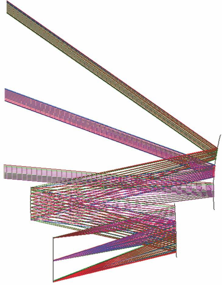
Fig. 1. Structural diagram of space-based detection optical system
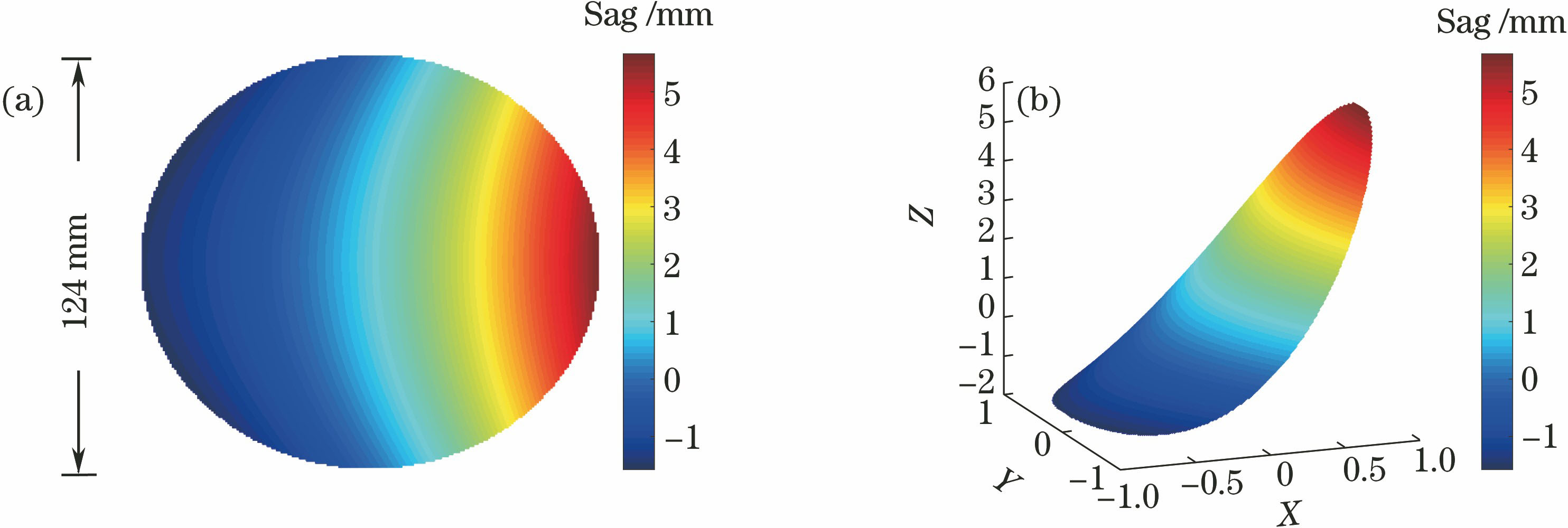
Fig. 2. Profile of Zernike freeform surface of primary mirror. (a) Two-dimensional; (b) three-dimensional
Fig. 3. Profile of XY freeform surface of tertiary mirror. (a) Two-dimensional; (b) three-dimensional
Fig. 4. Spot diagram of system
Fig. 5. Encircled energy distributions under different field views. (a) Field view of 0.5; (b) field view of 0.7; (c) edge field of view
Fig. 6. Detecting optical path. (a) CGH detecting optical path of freeform surface; (b) CGH unit in detecting optical path
Fig. 7. Lithography linear density of CGH and wave aberration of detecting system. (a) Lithographic linear density; (b) wave aberration
| No. | Polynomial | Aberration |
|---|
| Polar coordinate system | Cartesian coordinate system |
|---|
| 1 | 1 | 1 | Piston | | 2 | ρcos θ | x | x-tilt | | 3 | ρsin θ | y | y-tilt | | 4 | ρ2cos(2θ) | x2-y2 | 0° or 90° astigmatism | | 5 | 2ρ2-1 | 2(x2+y2)-1 | Defocus | | 6 | ρ2sin(2θ) | 2xy | 45° astigmatism | | 7 | ρ3cos(3θ) | x(x2-y2)-2xy2 | x-trefoil | | 8 | (3ρ2-2)ρcos θ | x[3(x2+y2)-2] | x-coma | | 9 | (3ρ2-2)ρsin θ | y[3(x2+y2)-2] | y-coma |
|
Table 1. Corresponding relationship between Zernike polynomials and aberration
| Parameter | Value |
|---|
| B | 8 | | Nc | 46 | | τ | 0.8 | | Integration time /s | 0.02 | | Eph /(10-19 J) | 3.4 | | fQE /% | 55 |
|
Table 2. Performance parameters of detector
| System parameter | Value |
|---|
| Focal length /mm | 64 | | Field of view /[(°) ×(°)] | 30×30 | | Entrance aperture /mm | 51 | | Equivalent visual magnitude | 9 | | Spectral band /nm | 400-900 |
|
Table 3. Main technical indexes of space-based optical detection system
| Surface | Radius /mm | Thickness /mm |
|---|
| Primary mirror | 175.4386 | -150 | | Secondary mirror | 333.3333 | 150 | | Tertiary mirror | -330.3704 | -125 |
|
Table 4. Initial structural parameters of optical system
| Mirror | Radius /mm | Distance /mm | Constant ofquadric surface | Y decenter /mm | x tilt /(°) |
|---|
| Primary mirror | 398.39 | -297.29 | -2.73 | 117.55 | 22.60 | | Secondary mirror | 1165.19 | 287.29 | 0 | 19.03 | 0 | | Tertiary mirror | -770.05 | -267.70 | -6.82 | -22.21 | 3.15 |
|
Table 5. Mirror parameters of optical system after optimization
| No. | Term | Coefficient |
|---|
| 1 | Z1 | 3.703732952805 | | 2 | Z2 | -0.005921378239 | | 3 | Z3 | 1.074318956926 | | 4 | Z4 | -0.000844676164 | | 5 | Z5 | 0.000225724509 | | 6 | Z6 | -7.298797621080×10⁻⁶ | | 7 | Z7 | 5.336916645650×10⁻⁸ | | 8 | Z8 | -2.419364792778×10⁻⁸ | | 9 | Z9 | 2.566383909345×10⁻⁶ | | 10 | Z10 | -1.197484299545×10⁻⁶ | | 11 | Z11 | 4.052592425289×10⁻¹⁰ | | 12 | Z12 | -2.946732238365×10⁻⁹ |
|
Table 6. Parameters of Zernike freeform surface of primary mirror
| Item | Coefficient | Item | Coefficient |
|---|
| Y | 0.0657280763771848 | X4Y | -1.508575293882×10⁻¹³ | | X2 | 0.000526216242287311 | X2Y3 | -1.246876764365×10⁻¹² | | Y2 | 0.000529147800335145 | Y5 | 1.859610071502×10⁻¹² | | X2Y | -2.14467235342657×10⁻⁸ | X6 | 8.860132888429×10⁻¹⁵ | | Y3 | -3.04871515062429×10⁻⁸ | X4Y2 | 2.549695693063×10⁻¹⁴ | | X4 | -1.89146570020516×10⁻⁹ | X2Y4 | 1.780628633470×10⁻¹⁴ | | X2Y2 | -3.7733664377066×10⁻⁹ | Y6 | 1.292338859180×10⁻¹⁴ | | Y4 | -1.69502835366705×10⁻⁹ | - | - |
|
Table 7. Parameters of XY freeform surface of tertiary mirror
| Mirror | Manufacture tolerance | Alignment tolerance |
|---|
| ΔR /mm | ΔK | RMS of shapeerror /λ | Decenter /mm | Tilt /rad | DisplacementΔY /mm |
|---|
| Primary mirror | 0.02 | 0.01 | 1/50 | 0.02 | 3×10⁻⁴ | 0.02 | | Second mirror | 0.005 | 0.002 | 1/50 | 0.01 | 1.5×10⁻⁴ | 0.02 | | Tertiary mirror | 0.02 | 0.008 | 1/50 | 0.02 | 3×10⁻⁴ | 0.08 |
|
Table 8. Distribution of system tolerance
| Field No. | Sagittal direction /(°) | Tangential direction /(°) | Design value /μm | Design tolerance /μm |
|---|
| 1 | 0 | -5 | 0.015416 | 0.023123 | | 2 | 0 | -20 | 0.010510 | 0.018538 | | 3 | 0 | -35 | 0.010699 | 0.018867 | | 4 | 5 | -5 | 0.009367 | 0.016026 | | 5 | 5 | -20 | 0.013022 | 0.022765 | | 6 | 5 | -35 | 0.007800 | 0.014165 | | 7 | 10 | -5 | 0.009585 | 0.017063 | | 8 | 10 | -20 | 0.013478 | 0.021934 | | 9 | 10 | -35 | 0.006847 | 0.012299 | | 10 | 15 | -5 | 0.009996 | 0.018456 | | 11 | 15 | -20 | 0.007032 | 0.012354 | | 12 | 15 | -35 | 0.006425 | 0.016219 |
|
Table 9. Performance of system tolerance