• Photonics Research
  • Vol. 10, Issue 8, 1971 (2022)
Li Liu1、2、†, Ruxue Wang1、2、†, Xuyi Zhao2、3, Wenfu Yu2、3, Yi Jin4、5、*, Qian Gong2、3、6、*, and Aimin Wu1、2、7、*
Author Affiliations
  • 1State Key Laboratory of Functional Materials for Informatics, Shanghai Institute of Microsystem and Information Technology, Chinese Academy of Sciences, Shanghai 200050, China
  • 2Center of Materials Science and Optoelectronics Engineering, University of Chinese Academy of Sciences, Beijing 100049, China
  • 3Key Laboratory of Terahertz Solid State Technology, Shanghai Institute of Microsystem and Information Technology, Chinese Academy of Sciences, Shanghai 200050, China
  • 4Centre for Optical and Electromagnetic Research and International Research Center for Advanced Photonics, College of Optical Science and Engineering, Zhejiang University, Hangzhou 310058, China
  • 5e-mail: jinyi_2008@zju.edu.cn
  • 6e-mail: qgong@mail.sim.ac.cn
  • 7e-mail: wuaimin@mail.sim.ac.cn
  • show less
    DOI: 10.1364/PRJ.462474 Cite this Article Set citation alerts
    Li Liu, Ruxue Wang, Xuyi Zhao, Wenfu Yu, Yi Jin, Qian Gong, Aimin Wu. Heterogeneously integrated quantum-dot emitters efficiently driven by a quasi-BIC-supporting dielectric nanoresonator[J]. Photonics Research, 2022, 10(8): 1971 Copy Citation Text show less

    Abstract

    Bound states in the continuum (BICs) can make subwavelength dielectric resonators sustain low radiation leakage, paving a new way to minimize the device size, enhance photoluminescence, and even realize lasing. Here, we present a quasi-BIC-supporting GaAs nanodisk with embedded InAs quantum dots as a compact bright on-chip light source, which is realized by heterogeneous integration, avoiding complex multilayered construction and subsequent mismatch and defects. The emitters are grown inside the nanodisk to match the mode field distribution to form strong light–matter interaction. One fabricated sample demonstrates a photoluminescence peak sustaining a quality factor up to 68 enhanced by the quasi-BIC, and the emitting effect can be further promoted by improving the epilayer quality and optimizing the layer-transferring process in the fabrication. This work provides a promising solution to building an ultracompact optical source to be integrated on a silicon photonic chip for high-density integration.

    1. INTRODUCTION

    Silicon photonics has been widely used in optical interconnection for telecom and datacom, as well as biosensing, while on-chip light sources are still a major challenge for high-density and low-cost integration. In contrast with silicon, III-V materials provide ideal gain properties. Hybrid lasers using III-V materials through the flip-chip technology [1] and the heterogeneous bonding technology [2] have been proven successful. The heterogeneous bonding technology provides robust alignment and post-CMOS process flexibility, as another promising scheme, and high-performance III-V quantum dots (QDs) [3,4] directly grown on silicon substrates by molecular beam epitaxy (MBE) technology [5] can enable cost-effective integration of low-threshold optical sources on silicon.

    The development of nanophotonics makes it ready for developing ultracompact on-chip sources on the other side. By confining light to a small volume based on localized resonance, subwavelength nanoresonators hold great promise [6,7]. Compared to metal nanoresonators, dielectric ones are preferred, since the material loss is negligible. Some innovative methods have been raised to design resonant dielectric nanoresonators [8] based on multipolar resonance [913]. Multipolar resonance makes a dielectric nanoresonator possess rich resonating ways, but it is weak in confining optical energy so that the corresponding quality factor (Q) is low. Bound states in the continuum (BICs) provide a solution way [1419]. BICs supported by periodic structures are perfect with Q unlimited, in theory. Later, the conception of BICs was introduced into dielectric nanoresonators to increase their Q values [20]. Due to limited size, BICs become quasi-BICs (also called supercavity modes) with limited Q values (up to several hundred). They are usually from the destructive interference between two supported modes, based on which the far-field leakage is efficiently weakened [21]. Based on quasi-BICs, dielectric nanoresonators have been used to enhance the light–matter interaction, such as lasing [2227] and nonlinear phenomena [2830].

    In this work, we propose to introduce the advantages of III-V QDs into a quasi-BIC-supporting dielectric nanodisk to construct a small on-chip bright light source. However, there are some parasitic problems if one directly grows III-V QDs on a silicon substrate. The different properties of thermal expansion and polarity existing between III-V and silicon materials may result in a high density of crystalline defects [31,32]. A relatively thick III-V buffer layer grown on a V-groove-patterned (001) silicon substrate [3336] is often used to overcome this mismatch, but this may cause the formation of thermal crack that may degrade the above III-V epilayer and induce the reliability issue in practical application. In addition, such a thick buffer layer may weaken the coupling from the active region to a silicon waveguide [37]. Here, we will combine the III-V-QD epitaxy and heterogenous bonding technologies. Based on such a combination, an individual quasi-BIC-supporting GaAs nanoresonator with embedded InAs QDs will be constructed. This architecture can improve the coupling between the QDs and the supported quasi-BIC to enhance the photoluminescence (PL).

    2. RESULTS AND DISCUSSION

    A single subwavelength dielectric nanodisk, supporting a quasi-BIC via the strong coupling between a Mie-like resonant mode and a Fabry–Perot (FP)-like resonant mode, can be designed following the Friedrich–Wintgen interference mechanism [21].

    To briefly illustrate the physical mechanism of the quasi-BIC formation, scattering simulation and Q calculation are performed for the dielectric nanodisk positioned in the free space, as illustrated in Fig. 1(a) and Fig. 1(b), respectively. The nanodisk is made of GaAs, and its height and radius are h and r, respectively. The numerical investigation is carried out by the time-domain finite-difference (FDTD) method.

    Resonating and scattering behavior of a single GaAs nanodisk. (a), (b) Schematic of the dielectric nanodisk in free space for scattering (a) and Q (b) simulation, respectively; (c) scattering cross section following the variation of the nanodisk radius and wavelength. The nanodisk’s height is fixed at h=560 nm. The size of each hollow circle is proportional to the Q factor of the corresponding resonant mode, and the black arrow indicates the appearance of a quasi-BIC at r/h=0.732. (d) Relation between the resonant wavelength corresponding to the two labeled bright stripes in (c) and the nanodisk radius. The three pairs of points, labeled as H1 and L1,H2 and L2, and H3 and L3, correspond to r=345 nm, 410 nm, and 440 nm, respectively. The two black dashed lines illustrate the developing trend of the strong coupling between the low-Q and high-Q modes. (e) Patterns of the six resonant modes are labeled by blue and red circles in (d). The YZ plane through the nanodisk axis is the observing plane and the electric amplitude is normalized. White lines show the nanodisk boundary.

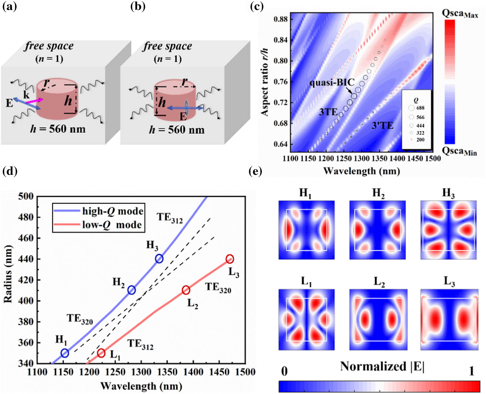
    Figure 1.Resonating and scattering behavior of a single GaAs nanodisk. (a), (b) Schematic of the dielectric nanodisk in free space for scattering (a) and Q (b) simulation, respectively; (c) scattering cross section following the variation of the nanodisk radius and wavelength. The nanodisk’s height is fixed at h=560  nm. The size of each hollow circle is proportional to the Q factor of the corresponding resonant mode, and the black arrow indicates the appearance of a quasi-BIC at r/h=0.732. (d) Relation between the resonant wavelength corresponding to the two labeled bright stripes in (c) and the nanodisk radius. The three pairs of points, labeled as H1 and L1,H2 and L2, and H3 and L3, correspond to r=345  nm, 410 nm, and 440 nm, respectively. The two black dashed lines illustrate the developing trend of the strong coupling between the low-Q and high-Q modes. (e) Patterns of the six resonant modes are labeled by blue and red circles in (d). The YZ plane through the nanodisk axis is the observing plane and the electric amplitude is normalized. White lines show the nanodisk boundary.

    When a transverse electric (TE) plane wave impinges on the nanodisk (the incident magnetic field is polarized along the cylinder axis), the scattering cross section as a function of the aspect ratio of the nanodisk (defined as r/h with h fixed at 560 nm) and the wavelength is shown in Fig. 1(c). The scattering cross section of Qsca for the nanodisk can be calculated by Qsca(λ)=Psca(λ)/[I(λ)S], where I(λ) is the intensity of the light source, and S=2rh is the cross-sectional area of the nanodisk. In the investigated wavelength range between 1100 and 1500 nm, the resonant behavior of the nanodisk strongly influences the scattering property, and multiple bright stripes appear in Fig. 1(c) from some special resonant modes. The two bright stripes labeled as 3TE and 3’TE, respectively, are interesting. Hollow circles of different sizes are put on the two stripes to represent the Q factor of the corresponding resonant mode, which is obtained by putting a point-like electric dipole inside the nanodisk as a pulse exciting source in the simulation. The Q factor can be derived as Q=f/Δf, where f is the central frequency and Δf is the full width at half-maximum at the resonant modes. Strong coupling exists between the two labeled stripes and then an anticrossing is formed. The Q factor of the top left labeled stripes becomes larger near the anticrossing region and the maximum value is up to about 688 when the aspect ratio of the nanodisk is about 0.732, i.e., r=410  nm (the resonant wavelength is 1281 nm). The bottom right stripe displays the opposite tendency.

    For clearer illumination, the resonant modes corresponding to the two labeled bright stripes are extracted and represented by two solid anticrossing curves corresponding to high-Q modes and low-Q modes in Fig. 1(d). Three pairs of resonant modes on the two solid curves are investigated to show the influence brought by the mode coupling, which are H1 and L1, H2 and L2, and H3 and L3, corresponding to r=345  nm, 410 nm, and 440 nm, respectively. By observing their main pattern parts, the two are nearly the standard TE320 and TE312 modes (the former is the Mie-like one, and the latter is the FP-like one), respectively. Here, we use a standard mode notation of TEnkm where indices n, k, and m are the azimuthal, radial, and axial indices of a cavity mode, respectively [30]. As the nanodisk is enlarged gradually, the resonant modes on curves 3TE and 3’TE form strong coupling and evolve as a hybridization of modes TE320 and TE312. As shown in Fig. 1(e), the electric patterns of resonant modes H2 and L2 embody this point well. Resonant mode H2 is just the so-called quasi-BIC, which has an enlarged Q factor and a reduced scattering cross section from the destructive canceling between modes TE320 and TE312 in the far-field scattering. As the nanodisk is further enlarged, the mode coupling becomes weaker again. By observing the electric patterns of resonant modes H3 and L3, one can see that the former becomes mode TE312 and the latter mode TE320. The Q values for the above three pairs of resonant modes, H1 and L1, H2 and L2, and H3 and L3, are 345 and 155, 688 and 102, 550 and 23, respectively. We have confirmed the formation of a quasi-BIC [21].

    A high-Q nanoresonator may be used to enhance PL. To fabricate such a subwavelength light source with embedded emitters, a new method combining InAs QDs growing and heterogeneous bonding is adopted, which is schematically shown in Figs. 2(a)–2(f). First, InAs QDs have grown on a GaAs (100) substrate by DCA P600 solid source MBE. This is started with a 500 nm GaAs buffer layer grown after native oxide desorption, above which a 500 nm AlAs sacrificial layer is grown. Then, a 10 nm gain material sandwiched by bottom and upper GaAs cladding layers is grown, which is called an active multilayer here. The gain material consists of 2 nm In0.35Ga0.65As for strain buffering, 2.2 mL InAs QDs, and 6 nm In0.35Ga0.65As for strain relaxing. The active multilayer is epitaxial from the bottom to the top, and the total thickness is about 560 nm, which is enough to construct one required nanodisk. Second, the sandwiched active multilayer is transferred and bonded. A thin protective photoresist is spin-coated on the GaAs cap layer. After baking, the whole chip is dipped into hydrofluoric acid solution (10%, mass fraction) to remove the sacrificial layer. Then, the active multilayer is lifted off [38] and transferred onto a silicon substrate with a 3 μm top oxide layer by direct bonding. Last, nanodisks of different radii are etched out. Hydrogen silsesquioxane (HSQ) resist is spun on the surface of the bonded active multilayer after the developing of the negative photoresist following electron beam lithography (EBL). The residual HSQ is used as a hard mask to etch out nanodisks by inductively coupled plasma deep reactive ion etching (ICP-DRIE). Finally, the HSQ mask is removed with buffered oxide etch.

    Fabricating GaAs nanodisks with embedded InAs QDs. (a) Growing InAs QDs. An active multilayer is grown on a GaAs (100) substrate by MBE, between which there is a 500 nm GaAs buffer layer and a 500 nm AlAs sacrificial layer. The active multilayer consists of a 275 nm GaAs bottom cladding layer, 10 nm InAs dot-in-well gain material (2 nm In0.35Ga0.65As layer for buffering strain, 2.2 mL InAs QDs, and 6 nm In0.35Ga0.65As layer for relaxing strain), and a 275 nm GaAs top cladding layer. (b) Lifting off the active multilayer by wet etching off the AlAs sacrificial layer; (c) bonding the active multilayer onto a silicon substrate with a 3 μm top oxide layer; (d) spunning HSQ on the transferred active multilayer and patterning it by EBL; (e) etching out nanodisks of different radii by ICP-DRIE; (f) removing the HSQ hard mask; (g) AFM images of the top surface before and after the transferring of the active multilayer; (h) SEM images of the fabricated nanodisks. The insets show the magnified top and side views of one nanodisk.

    Figure 2.Fabricating GaAs nanodisks with embedded InAs QDs. (a) Growing InAs QDs. An active multilayer is grown on a GaAs (100) substrate by MBE, between which there is a 500 nm GaAs buffer layer and a 500 nm AlAs sacrificial layer. The active multilayer consists of a 275 nm GaAs bottom cladding layer, 10 nm InAs dot-in-well gain material (2 nm In0.35Ga0.65As layer for buffering strain, 2.2 mL InAs QDs, and 6 nm In0.35Ga0.65As layer for relaxing strain), and a 275 nm GaAs top cladding layer. (b) Lifting off the active multilayer by wet etching off the AlAs sacrificial layer; (c) bonding the active multilayer onto a silicon substrate with a 3 μm top oxide layer; (d) spunning HSQ on the transferred active multilayer and patterning it by EBL; (e) etching out nanodisks of different radii by ICP-DRIE; (f) removing the HSQ hard mask; (g) AFM images of the top surface before and after the transferring of the active multilayer; (h) SEM images of the fabricated nanodisks. The insets show the magnified top and side views of one nanodisk.

    According to the atomic force microscope (AFM) measurement shown in Fig. 2(g), one can see that the surface roughness of the transferred active multilayer is no more than 10 nm, and the change of the roughness before and after the transferring process is negligible. And, as shown by the scanning electron microscope (SEM) measurement given in Fig. 2(h), the space of these fabricated nanodisks is about 50 μm to avoid the coupling influence between them, and these resonators are not perfect nanodisks in geometry due to imperfect fabrication.

    By investigating the above fabrication process, a fabricated nanodisk is directly supported by the 3 μm oxide layer. The existence of this dielectric spacer makes the environment of the GaAs nanodisk asymmetric. It pulls the confined optical energy inside the nanodisk downward and increases the leakage rate [39]. The nanodisk dimension is required to be moderately adjusted to make the Q factor corresponding to the sustained quasi-BIC as large as possible. As shown in Fig. 3, when r=400  nm and h=560  nm, the quasi-BIC is blueshifted to wavelength 1270 nm, and the corresponding Q factor is reduced to 229. Due to the large quality factor and small mode volume, the Purcell factor can be up to 11 [40]. When the electric dipole is put at the positions where the mode field is strong (i.e., the localized state density is large), the emitting may be enhanced most strongly. Thus, all the above-fabricated nanodisks are of height h=560  nm, and one of them has radius r=400  nm.

    Resonating behavior of a single GaAs nanodisk on a silicon substrate with a 3 μm oxide layer. Calculated Q and resonant wavelength versus nanodisk radius. The Q factor reaches its maximum value (229) for the optimal parameters (r=400 nm, h=560 nm) at wavelength 1270 nm.

    Figure 3.Resonating behavior of a single GaAs nanodisk on a silicon substrate with a 3 μm oxide layer. Calculated Q and resonant wavelength versus nanodisk radius. The Q factor reaches its maximum value (229) for the optimal parameters (r=400  nm, h=560  nm) at wavelength 1270 nm.

    In the characterization procedure, a home-built micro-photoluminescence (μ-PL) setup shown in Fig. 4(a) is used to image and measure the PL spectrum of the QDs embedded inside the nanodisk. An incident laser of wavelength 532 nm operating at 7.5 mW power is first expanded by a lens array to fill the aperture of the objective (20×, NA, 0.5) and focused onto a measured nanodisk. Both excited fluorescence and incident laser will then be collected by the same objective. A beam splitter is used to split the beam into two beams. Two lenses with different focuses are used to image (Retiga R6, Qimaging) and measure the PL of the nanodisk. A 1100 nm long-pass filter is used to filter the incident laser and allow the fluorescence to reach the spectrometer (SR-500i, ANDOR). The white beam is used to illuminate and position the nanodisk, which can be switched to the laser for locating the position of the laser and nanodisk. A PI platform (E-727, PI) is used to finely adjust the relative position of the laser and nanodisk to obtain the accurate spectrum. We first measure the PL from an unpatterned active multilayer of thickness 560 nm as a reference [Fig. 4(b)]. One can see that the PL is broadband, ranging from 1100 to 1400 nm.

    Schematic diagram of the optical setup for characterizing the μ-PL spectrum. (a) The nanodisk can be positioned by the home-built microscopy and captured by the camera (CCD). A continuous laser (532 nm) focused onto the sample by an objective (20×, NA=0.5) is used to excite the quasi-BIC by a single nanoresonator. A long-pass filter was inserted to reject the incident laser and only the fluorescence signal arrives in the spectrometer. (b) Normalized PL spectrum measured from a 560 nm active multilayer.

    Figure 4.Schematic diagram of the optical setup for characterizing the μ-PL spectrum. (a) The nanodisk can be positioned by the home-built microscopy and captured by the camera (CCD). A continuous laser (532 nm) focused onto the sample by an objective (20×, NA=0.5) is used to excite the quasi-BIC by a single nanoresonator. A long-pass filter was inserted to reject the incident laser and only the fluorescence signal arrives in the spectrometer. (b) Normalized PL spectrum measured from a 560 nm active multilayer.

    Then, the fabricated nanodisks are measured. Each nanodisk is pumped by a 532 nm continuous-wave (CW) laser, and the emitted PL is collected by a 20× microscope objective lens [Fig. 5(a)]. The corresponding SEM image of this nanodisk is shown in the inset of Fig. 5(a). The PL spectra for nanodisks with different radii are shown in Fig. 5(b). It is obviously observed that the shapes of these PL spectral curves are strongly affected by the variation of the nanodisk radius and narrowband PL peaks appear. When r=420  nm, the maximum enhancement of the PL is obtained, and the peak appears at wavelength 1281 nm. And, by comparing the intensity of PL peaks at different radii of the nanodisks, one can approximately estimate the enhancing effect on the PL up to 8 times. Obviously, the nanodisk is not a perfect cylinder, but an approximate frustum of a cone due to the fabrication imperfection, which may make the resonant behavior deviate from the ideal case. By estimating the PL peak width, one can achieve the Q factor of the corresponding resonant mode. Based on Lorentzian fitting, the Q factors corresponding to the strongest PL peaks for various GaAs nanodisks, are extracted and shown in Fig. 5(c). The maximum Q factor from the nanodisk of r=420  nm is 68.

    PL measurement for fabricated GaAs nanodisks. (a) Schematic of a GaAs nanodisk situated on a silicon substrate pumped by a 532 nm continuous laser. The inset is the exemplary SEM image of one fabricated nanodisk. (b) Measured PL spectra for various GaAs nanodisks of different radii; (c) Q factors are extracted from the measured PL spectra (black dots) and fitted by the Lorentzian curve for different GaAs nanodisks. The blue dotted line corresponds to the parameters at which the quasi-BIC appears.

    Figure 5.PL measurement for fabricated GaAs nanodisks. (a) Schematic of a GaAs nanodisk situated on a silicon substrate pumped by a 532 nm continuous laser. The inset is the exemplary SEM image of one fabricated nanodisk. (b) Measured PL spectra for various GaAs nanodisks of different radii; (c) Q factors are extracted from the measured PL spectra (black dots) and fitted by the Lorentzian curve for different GaAs nanodisks. The blue dotted line corresponds to the parameters at which the quasi-BIC appears.

    There are two reasons for the deviation between the theoretical prediction and the experimental result. One is that the fabrication error, which includes the side angle α of the nanodisk and the inclination angle θ between the nanodisk and substrate, can influence the resonant behavior of a GaAs nanodisk, as indicated in Fig. 6(a). As α decreases from 90 deg to 79 deg and θ increases from 0 deg to 10 deg, the Q factor decreases to about 180 and 195, respectively. In practical fabrication, nonzero θ may appear, which induces a larger leaky rate by making the surrounding more asymmetric. Moreover, the GaAs material is assumed to be lossless in the simulation. However, in practice, the fabricated GaAs material is a bit lossy and there is also scattering loss from the embedded QDs. As shown in Fig. 6(b), the fabricated active multilayer has a measured effective complex refractive index of n=3.45 and k=0.055 around wavelength 1281 nm. Figure 6(c) shows that the Q factor of a GaAs nanodisk strongly depends on the material losses and could be substantially decreased. Thus, the material loss and fabrication error are not ignorable for a practical resonant nanodisk, but the imperfection of the fabrication has limited influence on the Q factor.

    Influence of material loss and fabrication error on GaAs nanodisks. (a) The two angles representing imperfect fabrication may degrade the Q factor of the supported quasi-BIC. The insets are illustrating the side angle (θ) and the inclination angle (α) for the nanodisk, respectively. (b) Measured refractive index of the active multilayer. The black solid line represents the real part of the refractive index, while the red solid line is the imaginary part of the refractive index. The active multilayer has a refractive index of about n=3.45 with an unignorable material loss k=0.055 in the wavelength range from 1100 to 1400 nm. (c) Q factors for different nanodisks are calculated according to the measured complex refractive index in (b).

    Figure 6.Influence of material loss and fabrication error on GaAs nanodisks. (a) The two angles representing imperfect fabrication may degrade the Q factor of the supported quasi-BIC. The insets are illustrating the side angle (θ) and the inclination angle (α) for the nanodisk, respectively. (b) Measured refractive index of the active multilayer. The black solid line represents the real part of the refractive index, while the red solid line is the imaginary part of the refractive index. The active multilayer has a refractive index of about n=3.45 with an unignorable material loss k=0.055 in the wavelength range from 1100 to 1400 nm. (c) Q factors for different nanodisks are calculated according to the measured complex refractive index in (b).

    3. CONCLUSIONS

    In conclusion, we have designed and fabricated a GaAs nanodisk sustaining a quasi-BIC on a silicon substrate. InAs QDs, bringing their particular advantages, are adopted to act as emitters. They are flexibly embedded inside the nanodisk to overlap with the strong field part of the quasi-BIC to efficiently enhance the PL emission. Although the Q factor of the strongest PL peak is just 68 in the experiment due to the large material loss, it is assured to make it tend to the ideal value by optimizing the material preparation. Currently, many works are carried out to integrate QDs into silicon active devices as a prospective way. The proposed nanodevice provides a subwavelength light source, even a nanolaser, compatible with other silicon photonic devices. In the future, InAs QDs may be introduced into periodic structures supporting delocalized BICs as a gain material.

    References

    [1] L. Zimmermann, G. B. Preve, K. Voigt, G. Winzer, J. Kreissl, L. Moerl, C. Stamatiadis, L. Stampoulidis, H. Avramopoulos. High-precision flip-chip technology for all optical wavelength conversion using SOI photonic circuit. 8th IEEE International Conference on Group IV Photonics, 237-239(2011).

    [2] G. H. Duan, C. Jany, A. L. Liepvre, A. Accard, M. Lamponi, D. Make, P. Kaspar, G. Levaufre, N. Girard, F. Lelarge. Hybrid III-V on silicon lasers for photonic integrated circuits on silicon. IEEE J. Sel. Top. Quantum Electron., 20, 158-170(2014).

    [3] J. C. Norman, D. Jung, Y. Wan, E. John. Bowers perspective: the future of quantum dot photonic integrated circuits. APL Photon., 3, 030901(2018).

    [4] T. Zhou, M. Tang, G. Xiang, X. Fang, X. Liu, B. Xiang, S. Hark, M. Martin, M.-L. Touraton, T. Baron, Y. Lu, S. Chen, H. Liu, Z. Zhang. Ultra-low threshold InAs/GaAs quantum dot microdisk lasers on planar on-axis Si (001) substrates. Optica, 6, 430-435(2019).

    [5] K. Nishi, K. Takemasa, M. Sugawara, Y. Arakawa. Development of quantum dot lasers for data-com and silicon photonics applications. IEEE J. Sel. Top. Quantum Electron., 23, 1901007(2017).

    [6] M. Ren-Min, R. F. Oulton. Applications of nanolasers. Nat. Nanotechnol., 14, 12-22(2019).

    [7] I. Staude, T. Pertsch, Y. S. Kivshar. All-dielectric resonant meta-optics lightens up. ACS Photon., 6, 802-814(2019).

    [8] A. I. Kuznetsov, A. E. Miroshnichenko, M. L. Brongersma, Y. S. Kivshar, B. Luk’yanchuk. Optically resonant dielectric nanostructures. Science, 354, aag2472(2016).

    [9] V. Rutckaia, F. Heyroth, A. Novikov, M. Shaleev, M. Petrov, J. Schilling. Quantum dot emission driven by Mie resonances in silicon nanostructures. Nano Lett., 17, 6886-6892(2017).

    [10] E. Tiguntseva, K. Koshelev, A. Furasova, P. Tonkaev, V. Mikhailovskii, E. V. Ushakova, D. G. Baranov, T. Shegai, A. A. Zakhidov, Y. Kivshar, S. V. Makarov. Room-temperature lasing from Mie-resonant non-plasmonic nanoparticles. ACS Nano, 14, 8149-8156(2020).

    [11] T. X. Hoang, S. T. Ha, Z. Pan, W. K. Phua, R. Paniagua-Domínguez, C. E. Png, H.-S. Chu, A. I. Kuznetsov. Collective Mie resonances for directional on-chip nanolasers. Nano Lett., 20, 5655-5661(2020).

    [12] V. Rutckaia, F. Heyroth, G. Schmidt, A. Novikov, M. Shaleev, R. S. Savelev, J. Schilling, M. Petrov. Coupling of germanium quantum dots with collective sub-radiant modes of silicon nanopillar arrays. ACS Photon., 8, 209-217(2021).

    [13] H. Sugimoto, M. Fujii. Colloidal Mie resonant silicon nanoparticles. Nanotechnology, 32, 452001(2021).

    [14] C. W. Hsu, B. Zhen, A. D. Stone, J. D. Joannopoulos, M. Soljačić. Bound states in the continuum. Nat. Rev. Mater., 1, 16048(2016).

    [15] Z. F. Sadrieva, I. S. Sinev, K. L. Koshelev, A. Samusev, I. V. Iorsh, O. Takayama, R. Malureanu, A. A. Bogdanov, A. V. Lavrinenko. Transition from optical bound states in the continuum to leaky resonances: role of substrate and roughness. ACS Photon., 4, 723-727(2017).

    [16] A. Kodigala, T. Lepetit, Q. Gu, B. Bahari, Y. Fainman, K. Boubacar. Lasing action from photonic bound states in continuum. Nature, 541, 196-199(2017).

    [17] K. Koshelev, A. Bogdanov, Y. Kivshar. Meta-optics and bound states in the continuum. Sci. Bull., 64, 836-842(2019).

    [18] J.-H. Yang, Z.-T. Huang, D. N. Maksimov, P. S. Pankin, I. V. Timofeev, K.-B. Hong, H. Li, J.-W. Chen, C.-Y. Hsu, Y.-Y. Liu, T.-C. Lu, T.-R. Lin, C.-S. Yang, K.-P. Chen. Low-threshold bound state in the continuum lasers in hybrid lattice resonance metasurfaces. Laser Photon. Rev., 15, 2100118(2021).

    [19] S. Cao, Y. Jin, H. Dong, T. Guo, J. He, S. He. Enhancing single photon emission through quasi-bound states in the continuum of monolithic hexagonal boron nitride metasurface. J. Phys. Mater., 4, 035001(2021).

    [20] M. V. Rybin, K. L. Koshelev, Z. F. Sadrieva, K. B. Samusev, A. A. Bogdanov, M. F. Limonov, Y. S. Kivshar. High-Q supercavity modes in subwavelength dielectric resonators. Phys. Rev. Lett., 119, 243901(2017).

    [21] A. A. Bogdanov, K. L. Koshelev, P. V. Kapitanova, M. V. Rybin, S. A. Gladyshev, Z. F. Sadrieva, K. B. Samusev, Y. S. Kivshar, F. Mikhail. Bound states in the continuum and Fano resonances in the strong mode coupling regime. Adv. Photon., 1, 016001(2019).

    [22] S. T. Ha, Y. H. Fu, N. K. Emani, Z. Pan, R. M. Bakker, R. Paniagua-Dominguez, A. I. Kuznetsov. Directional lasing in resonant semiconductor nanoantenna arrays. Nat. Nanotechnol., 13, 1042-1047(2018).

    [23] C. Huang, C. Zhang, S. Xiao, Y. Wang, Y. Fan, Y. Liu, N. Zhang, G. Qu, H. Ji, J. Han, L. Ge, Y. Kivshar, Q. Song. Ultrafast control of vortex microlasers. Science, 367, 1018-1021(2020).

    [24] V. Mylnikov, S. T. Ha, Z. Pan, V. Valuckas, R. Paniagua-Domínguez, H. V. Demir, A. I. Kuznetsov. Lasing action in single subwavelength particles supporting supercavity modes. ACS Nano, 14, 7338-7346(2020).

    [25] M. Wu, L. Ding, R. P. Sabatini, L. K. Sagar, G. Bappi, R. Paniagua-Domínguez, E. H. Sargent, A. I. Kuznetsov. Bound state in the continuum in nanoantenna-coupled slab waveguide enables low-threshold quantum-dot lasing. Nano Lett., 21, 9754-9760(2021).

    [26] W. Bi, X. Zhang, M. Yan, L. Zhao, T. Ning, Y. Huo. Low-threshold and controllable nanolaser based on quasi-BIC supported by an all-dielectric eccentric nanoring structure. Opt. Express, 29, 12634-12643(2021).

    [27] R. Heilmann, G. Salerno, J. Cuerda, T. K. Hakala, P. Törmä. Quasi-BIC mode lasing in a quadrumer plasmonic lattice. ACS Photon., 9, 224-232(2022).

    [28] H. K. Gandhi, D. Rocco, L. Carletti, C. De Angelis. Gain-loss engineering of bound states in the continuum for enhanced nonlinear response in dielectric nanocavities. Opt. Express, 28, 3009-3016(2020).

    [29] S. D. Krasikov, A. A. Bogdanov, I. V. Iorsh. Nonlinear bound states in the continuum of a one-dimensional photonic crystal slab. Phys. Rev. B, 97, 224309(2018).

    [30] K. Koshelev, S. Kruk, E. Melik-Gaykazyan, J.-H. Choi, A. Bogdanov, H.-G. Park, Y. Kivshar. Subwavelength dielectric resonators for nonlinear nanophotonics. Science, 367, 288-292(2020).

    [31] H. Kroemer. Polar-on-nonpolar epitaxy. J. Cryst. Growth, 81, 193-204(1987).

    [32] M. Liao, S. Chen, J.-S. Park, A. Seeds, H. Liu. III-V quantum-dot lasers monolithically grown on silicon. Semicond. Sci. Technol., 33, 123002(2018).

    [33] Y. Wan, Q. Li, A. Y. Liu, A. C. Gossard, J. E. Bowers, E. L. Hu, K. M. Lau. Optically pumped 1.3 μm room-temperature InAs quantum-dot micro-disk lasers directly grown on (001) silicon. Opt. Lett., 41, 1664-1667(2016).

    [34] Y. Wan, J. Norman, Q. Li, M. J. Kennedy, D. Liang, C. Zhang, D. Huang, Z. Zhang, A. Y. Liu, A. Torres, D. Jung, A. C. Gossard, E. L. Hu, K. M. Lau, J. E. Bowers. 1.3  μm submilliamp threshold quantum dot micro-lasers on Si. Optica, 4, 940-944(2017).

    [35] J. Kwoen, B. Jang, J. Lee, T. Kageyama, K. Watanabe, Y. Arakawa. All MBE grown InAs/GaAs quantum dot lasers on on-axis Si (001). Opt. Express, 26, 11568-11576(2018).

    [36] B. Zhang, W.-Q. Wei, J.-H. Wang, H.-L. Wang, Z. Zhao, L. Liu, H. Cong, Q. Feng, H. Liu, T. Wang, J.-J. Zhang. O-band InAs/GaAs quantum-dot microcavity laser on Si (001) hollow substrate by in-situ hybrid epitaxy. AIP Adv., 9, 015331(2019).

    [37] J. E. Bowers, J. T. Bovington, A. Y. Liu, A. C. Gossard. A path to 300 mm hybrid silicon photonic integrated circuits. Optical Fiber Communication Conference, Th1C.1(2014).

    [38] E. Yablonovitch, T. Gmitter, J. P. Harbison, R. Bhat. Extreme selectivity in the lift-off of epitaxial GaAs films. Appl. Phys. Lett., 51, 222-2224(1987).

    [39] J. van de Groep, A. Polman. Designing dielectric resonators on substrates: combining magnetic and electric resonances. Opt. Express, 21, 26285-26302(2013).

    [40] R. Colom, F. Binkowski, F. Betz, Y. Kivshar, S. Burger. Enhanced Purcell factor for nanoantennas supporting interfering resonances. Phys. Rev. Res., 4, 023189(2022).

    Li Liu, Ruxue Wang, Xuyi Zhao, Wenfu Yu, Yi Jin, Qian Gong, Aimin Wu. Heterogeneously integrated quantum-dot emitters efficiently driven by a quasi-BIC-supporting dielectric nanoresonator[J]. Photonics Research, 2022, 10(8): 1971
    Download Citation