
Qiwen Liu, Guodong Liu, Zihang Li, Changpeng Xie. Preparation and Properties of Superhydrophobic Surface of Magnesium Alloy by Nanosecond Laser[J]. Laser & Optoelectronics Progress, 2022, 59(5): 0514004
- Laser & Optoelectronics Progress
- Vol. 59, Issue 5, 0514004 (2022)
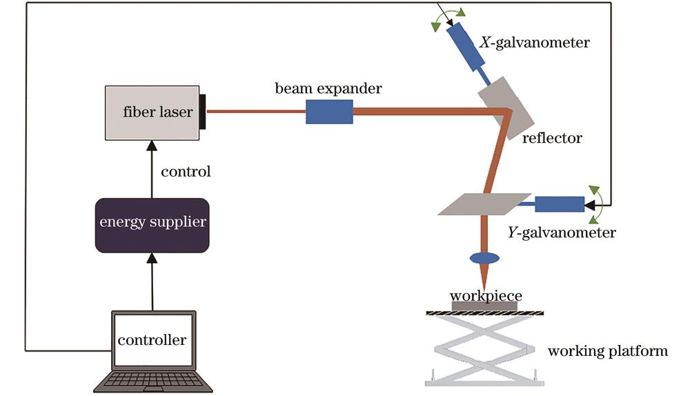
Fig. 1. Schematic of laser processing equipment and laser path
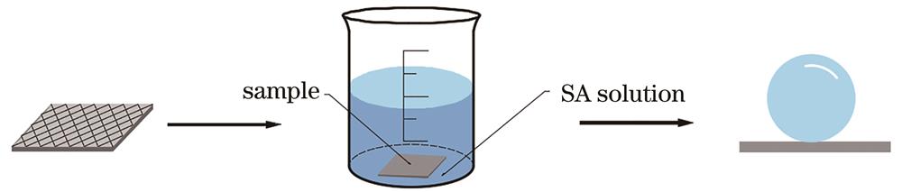
Fig. 2. Schematic of superhydrophobic surface preparation
Fig. 3. Sample morphology under different energy densities. (a) 0
Fig. 4. Three-dimensional topography under different energy densities. (a) 0
Fig. 5. Contact angle and sliding angle of magnesium alloy surface under different laser power densities
Fig. 6. EDS diagrams of magnesium alloy samples before and after superhydrophobic treatment. (a) Original magnesium alloy; (b) superhydrophobic magnesium alloy
Fig. 7. Comparison of polarization curve results between untreated surface and superhydrophobic treated surface
Fig. 8. Wetting model of NaCl solution on superhydrophobic magnesium alloy surface
Fig. 9. Variation diagram of contact angle and sliding angle of superhydrophobic magnesium alloy with time
Fig. 10. Self-cleaning diagram of superhydrophobic magnesium alloy
Fig. 11. Self-cleaning effect of magnesium alloy surface. (a) Original magnesium alloy surface; (b) superhydrophobic magnesium alloy surface
|
Table 1. Measurement results of corrosion voltage, current density, and corrosion rate of untreated surface and superhydrophobic treated surface

Set citation alerts for the article
Please enter your email address
© Copyright 2018-2021 | Chinese Laser Press. All Rights Reserved 沪ICP备15018463号-20