• Photonics Research
  • Vol. 6, Issue 11, 1056 (2018)
Quanlong Yang1, Xieyu Chen1, Quan Xu1, Chunxiu Tian2, Yuehong Xu1, Longqing Cong3, Xueqian Zhang1, Yanfeng Li1, Caihong Zhang4, Xixiang Zhang2, Jiaguang Han1、*, and Weili Zhang1、5、6
Author Affiliations
  • 1Center for Terahertz Waves and College of Precision Instrument and Optoelectronics Engineering, Tianjin University, and the Key Laboratory of Optoelectronics Information and Technology Tianjin, Ministry of Education of China, Tianjin 300072, China
  • 2Physical Science and Engineering Division, King Abdullah University of Science and Technology, Thuwal 23955-6900, Saudi Arabia
  • 3Division of Physics and Applied Physics, School of Physical and Mathematical Sciences, Nanyang Technological University, 21 Nanyang Link, Singapore 637371, Singapore
  • 4Research Institute of Superconductor Electronics (RISE), School of Electronic Science and Engineering, Nanjing University, Nanjing 210093, China
  • 5School of Electrical and Computer Engineering, Oklahoma State University, Stillwater, Oklahoma 74078, USA
  • 6e-mail: weili.zhang@okstate.edu
  • show less
    DOI: 10.1364/PRJ.6.001056 Cite this Article Set citation alerts
    Quanlong Yang, Xieyu Chen, Quan Xu, Chunxiu Tian, Yuehong Xu, Longqing Cong, Xueqian Zhang, Yanfeng Li, Caihong Zhang, Xixiang Zhang, Jiaguang Han, Weili Zhang. Broadband terahertz rotator with an all-dielectric metasurface[J]. Photonics Research, 2018, 6(11): 1056 Copy Citation Text show less
    (a) Conceptual description of the metasurface based on two identical dielectric antennas to manipulate the polarization of the terahertz wave. α and β represent the orientations of two dielectric antennas (marked by the orange arrows), and γ is the effective optical axis orientation from the superposition of two antennas (marked by the navy arrow). (b) Schematic illustration of the two silicon antennas with geometrical parameters W=45 μm, L=180 μm, H=200 μm, and period P=375 μm. (c),(d) Schematic diagrams for high-quality polarization generation. Without introducing the phase gradient, both the x-polarized and y-polarized light propagates in the normal direction forming dispersive polarization states within the frequency range of interest. The phase gradient enables spatial separation of the two orthogonal polarization components, giving rise to pure linearly polarized components within a broad frequency range.
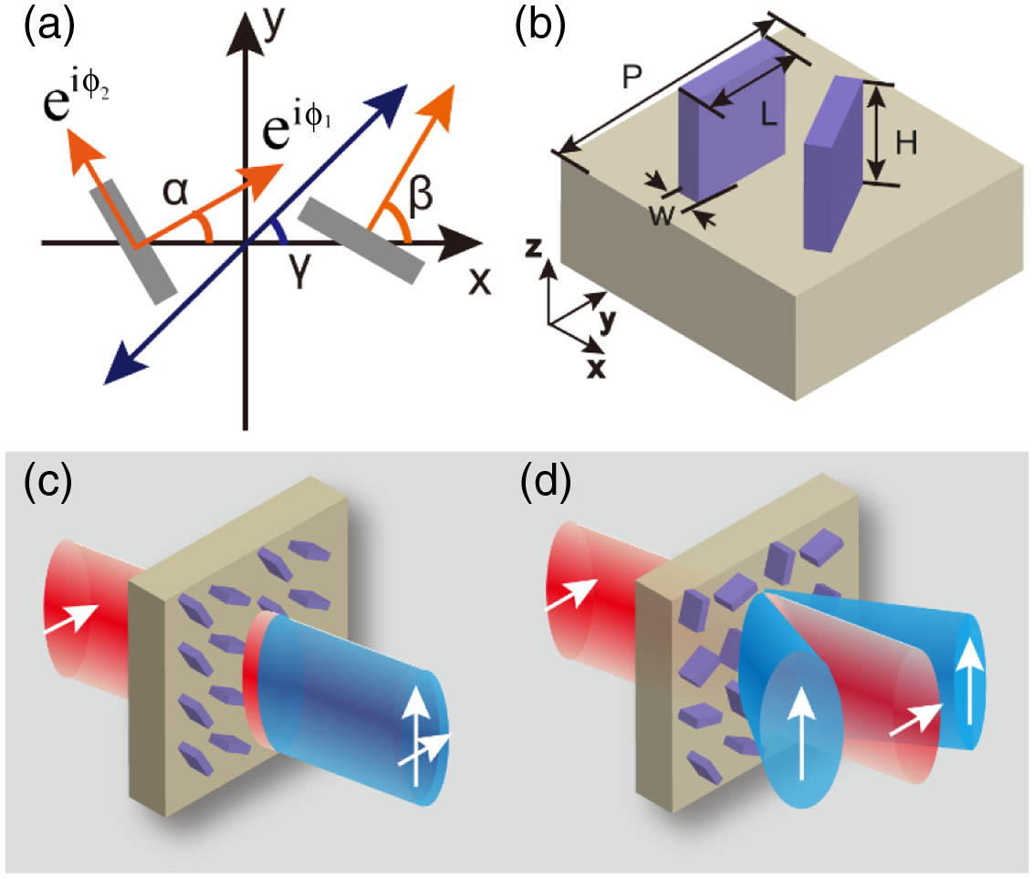
    Fig. 1. (a) Conceptual description of the metasurface based on two identical dielectric antennas to manipulate the polarization of the terahertz wave. α and β represent the orientations of two dielectric antennas (marked by the orange arrows), and γ is the effective optical axis orientation from the superposition of two antennas (marked by the navy arrow). (b) Schematic illustration of the two silicon antennas with geometrical parameters W=45  μm, L=180  μm, H=200  μm, and period P=375  μm. (c),(d) Schematic diagrams for high-quality polarization generation. Without introducing the phase gradient, both the x-polarized and y-polarized light propagates in the normal direction forming dispersive polarization states within the frequency range of interest. The phase gradient enables spatial separation of the two orthogonal polarization components, giving rise to pure linearly polarized components within a broad frequency range.
    (a)–(c) Optical images of the ultrabroadband dielectric metasurface rotators S1, S2, and S3. The red arrows denote the optical axis of rotators. (d)–(f) Simulated electric field distributions of the output y-polarization component through rotator S3 at 0.6, 0.73, and 1.0 THz, respectively, with the x-polarized incidence. (g)–(i) Corresponding diffraction angles at 0.6, 0.73, and 1.0 THz.
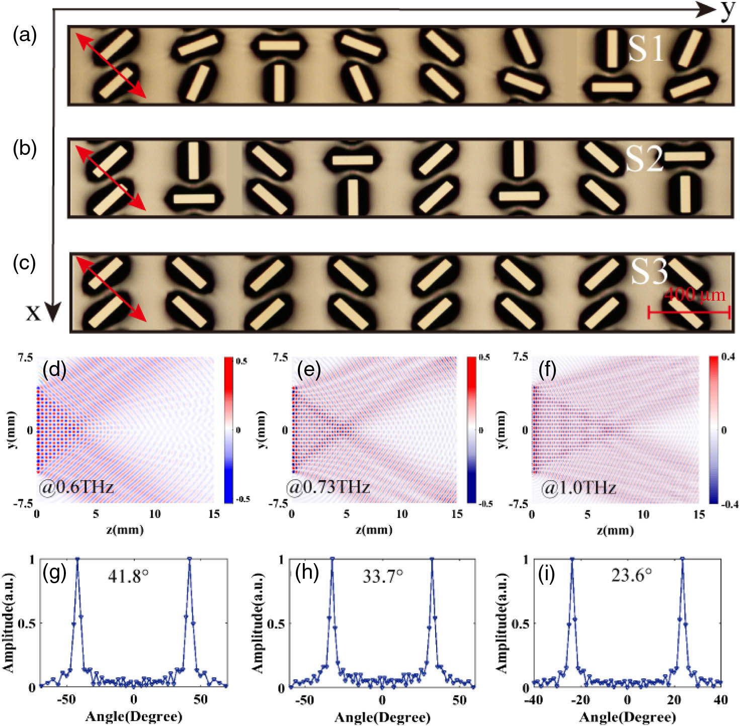
    Fig. 2. (a)–(c) Optical images of the ultrabroadband dielectric metasurface rotators S1, S2, and S3. The red arrows denote the optical axis of rotators. (d)–(f) Simulated electric field distributions of the output y-polarization component through rotator S3 at 0.6, 0.73, and 1.0 THz, respectively, with the x-polarized incidence. (g)–(i) Corresponding diffraction angles at 0.6, 0.73, and 1.0 THz.
    (a)–(c) Measured cross-polarized transmission spectra of the three rotators S1–S3 versus the deflection angle. White dashed lines represent the theoretically calculated deflection angles. (d)–(f) Corresponding measured transmission spectra of the copolarized component.
    Fig. 3. (a)–(c) Measured cross-polarized transmission spectra of the three rotators S1–S3 versus the deflection angle. White dashed lines represent the theoretically calculated deflection angles. (d)–(f) Corresponding measured transmission spectra of the copolarized component.
    (a) Quality analysis of the output polarization state of rotator S3 with the copolarized incidence. The navy line is obtained from theoretical calculation, and measured values are represented by the red circle dots. (b) Measured cross-polarization efficiencies of S1, S2, and S3.
    Fig. 4. (a) Quality analysis of the output polarization state of rotator S3 with the copolarized incidence. The navy line is obtained from theoretical calculation, and measured values are represented by the red circle dots. (b) Measured cross-polarization efficiencies of S1, S2, and S3.
    (a) Measured transmission spectra of S3 under the circular polarization incidence. (b),(c) Measured cross-polarized and copolarized transmission spectra of sample S4 versus the deflection angle, respectively. (d),(e) Corresponding measured transmission spectra of S5. Insets are the optical image of rotators S4 and S5, and the red arrows denote the optical axis of the rotators.
    Fig. 5. (a) Measured transmission spectra of S3 under the circular polarization incidence. (b),(c) Measured cross-polarized and copolarized transmission spectra of sample S4 versus the deflection angle, respectively. (d),(e) Corresponding measured transmission spectra of S5. Insets are the optical image of rotators S4 and S5, and the red arrows denote the optical axis of the rotators.
    Quanlong Yang, Xieyu Chen, Quan Xu, Chunxiu Tian, Yuehong Xu, Longqing Cong, Xueqian Zhang, Yanfeng Li, Caihong Zhang, Xixiang Zhang, Jiaguang Han, Weili Zhang. Broadband terahertz rotator with an all-dielectric metasurface[J]. Photonics Research, 2018, 6(11): 1056
    Download Citation