1Center for Terahertz Waves and College of Precision Instrument and Optoelectronics Engineering, Tianjin University, and the Key Laboratory of Optoelectronics Information and Technology Tianjin, Ministry of Education of China, Tianjin 300072, China
2Physical Science and Engineering Division, King Abdullah University of Science and Technology, Thuwal 23955-6900, Saudi Arabia
3Division of Physics and Applied Physics, School of Physical and Mathematical Sciences, Nanyang Technological University, 21 Nanyang Link, Singapore 637371, Singapore
4Research Institute of Superconductor Electronics (RISE), School of Electronic Science and Engineering, Nanjing University, Nanjing 210093, China
5School of Electrical and Computer Engineering, Oklahoma State University, Stillwater, Oklahoma 74078, USA
Polarization manipulation is essential in developing cutting-edge photonic devices ranging from optical communication displays to solar energy harvesting. Most previous works for efficient polarization control cannot avoid utilizing metallic components that inevitably suffer from large ohmic loss and thus low operational efficiency. Replacing metallic components with Mie resonance-based dielectric resonators will largely suppress the ohmic loss toward high-efficiency metamaterial devices. Here, we propose an efficient approach for broadband, high-quality polarization rotation operating in transmission mode with all-dielectric metamaterials in the terahertz regime. By separating the orthogonal polarization components in space, we obtain rotated output waves with a conversion efficiency of 67.5%. The proposed polarization manipulation strategy shows impressive robustness and flexibility in designing metadevices of both linear- and circular-polarization incidences.
1. INTRODUCTION
Polarization as one of the intrinsic properties of light plays a significant role in modern photonic systems. Polarizers and wave plates are routinely used in optical imaging, communication, and signal processing. In particular, wave plates, which transform the polarization direction or states of polarization, enable more freedoms of polarization manipulation. Traditional polarization devices based on birefringent crystals or prisms have intrinsic limitations with their bulky size and narrow operation band that prevent them from being integrated into miniature and broadband photonic systems. Metasurfaces consisting of an artificially engineered antenna array provide an alternative approach to arbitrarily manipulate the polarization of light [1–7]. Great efforts have been devoted to improving the quality of polarization manipulation on the basis of metasurfaces, such as broadening the bandwidth [8,9], reducing the losses [10,11], and seeking for ultrafast dynamic solutions [12–14]. However, most of the previous discussions were based on plasmonic metasurfaces that suffer from ohmic loss and thus limited operational efficiency. One of the commonly adopted strategies to improve efficiency and operation bandwidth is via a metal–insulator–metal sandwich configuration, which can only operate in the reflection mode [15–17]. Another solution for transmission application is the stack of multilayer metasurfaces [18–20]. However, the efficiency is still limited by the plasmonic resonator with a large ohmic loss. One approach to avoid ohmic loss is to replace metallic components with dielectric antennas [21,22]. Owing to Mie resonances, magnetic resonances together with electric resonances provide a new approach to realize full phase control [23–26].
Here, we propose a metamaterial scheme for high-efficiency polarization manipulation by applying the Pancharatnam–Berry (P–B) phase that operates for both linear and circular polarization states. In fact, by applying the P–B phase, several applications have been demonstrated with a single-layer metasurface for right- and left-circularly polarized (RCP and LCP) light over a broadband frequency regime [27–30]. In our work, by introducing a phase gradient for the cross-polarized component, we separate the orthogonal polarization components in space covering 0.5–1.4 THz. Our systematic studies also reveal that the proposed scheme shows excellent robustness and polarization manipulation performance.
2. THEORETICAL ANALYSIS
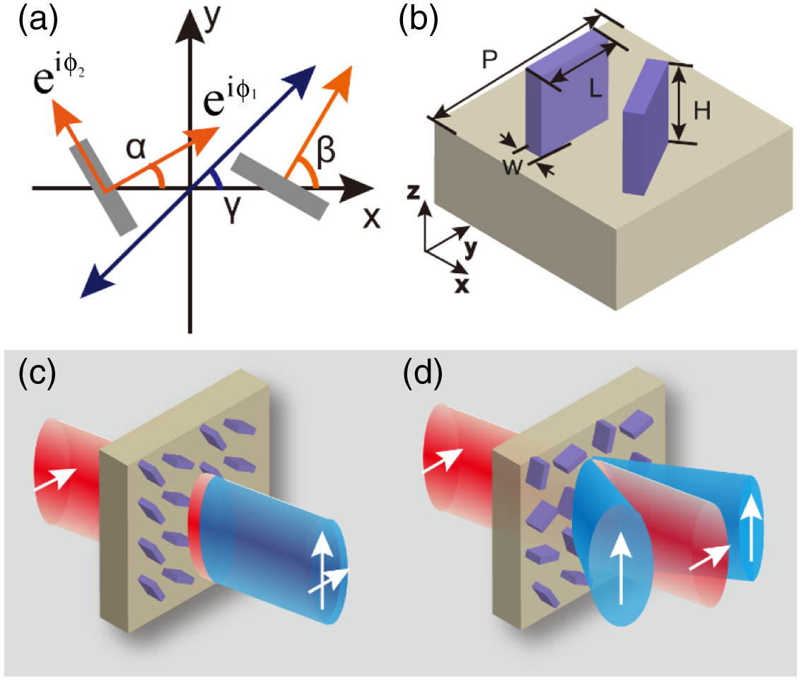
As schematically illustrated in Fig. 1(a), the proposed structure is based on a pair of rectangular-shaped silicon pillars. It is known that the optical response of one single-silicon pillar could be described by the standard Jones matrix as where represents the angle of the pillar relative to the axis; and are the phase accumulations for light propagation with polarization along the short and long axes of the silicon pillar, respectively. Concerning the pair of identical silicon pillars, one more freedom will be introduced with rotation angle .
Sign up for Photonics Research TOC. Get the latest issue of Photonics Research delivered right to you!Sign up now
Figure 1.(a) Conceptual description of the metasurface based on two identical dielectric antennas to manipulate the polarization of the terahertz wave. and represent the orientations of two dielectric antennas (marked by the orange arrows), and is the effective optical axis orientation from the superposition of two antennas (marked by the navy arrow). (b) Schematic illustration of the two silicon antennas with geometrical parameters μ, μ, μ, and period μ. (c),(d) Schematic diagrams for high-quality polarization generation. Without introducing the phase gradient, both the -polarized and -polarized light propagates in the normal direction forming dispersive polarization states within the frequency range of interest. The phase gradient enables spatial separation of the two orthogonal polarization components, giving rise to pure linearly polarized components within a broad frequency range.
First, consider a typical case by assuming and , where is an arbitrary angle and is the relative rotation angle between the adjacent pillars. Then the Jones matrix of two uncoupled silicon pillars can be expressed as Here, we ignore the coupling effects between the pillars. Under the linearly polarized incidence with a polarization angle , the output electric field through the pillar pair is obtained by As indicated by Eq. (3), the polarization states of the output light are determined by three parameters: , , and . If a phase gradient is introduced into the lateral neighboring pillar pairs ( is an integer, is the periodicity, and is the length along the axis), it is obvious that the output of the rotator under the first case can be divided into two parts: one is the copolarized component without a phase gradient, and the other one is the cross-polarized component with a phase gradient of . Here, the copolarized component will emerge along the axis, while the cross-polarized one will be deflected into different diffraction orders according to the generalized Snell’s law [31,32]. Assuming , we obtain a perfect rotation of incident polarization to the orthogonal direction with where the copolarized component then will be cancelled, and the silicon pillar pairs will play the role of a metasurface rotator with the optical axis .
Next, we take another interesting case into account. Where we assume and , and an incident linearly polarized light with an angle of , the output polarization state could be obtained by In the case of , a perfect polarization rotation with an angle of could be achieved.
We note that the above discussion is generally valid whether the incident light is linearly or circularly polarized. For a circularly-polarized incidence, we have with for RCP and for LCP, which describes the circular polarization with opposite polarization states.
The significance of introducing a phase gradient is reflected in the scenario when the phase difference between the orthogonal polarizations along the long and short axes in the silicon pillar deviates from , which is inevitable in fabrication inaccuracy. In this case, the polarization rotation will not be perfect, and both copolarized and cross-polarized components will be induced, which degrades the quality of the output polarization state, as depicted in Fig. 1(c). By combining with the P–B phase, the phase gradient is introduced for the cross-polarized component by rotating the orientation angles of the silicon pillars, and thus the cross-polarized component will be separated from the copolarized component in space, which improves the desired polarization quality. As shown in Fig. 1(d), the silicon pillar rotates clockwise with a specific angle versus the axis in a row, while it rotates counterclockwise to obtain the continuous phase gradient in the neighboring row. Compared to the previous P–B phase studies that only worked under the circular polarization base, our design works for both linear and circular polarization incidences.
3. SIMULATION RESULTS
To show the feasibility of the proposed strategies described above, five different samples (S1–S5) were designed and fabricated. Figures 2(a)–2(c) show the fabricated samples S1, S2, and S3, which are adopted to verify the first case of and . The silicon pillars in all the samples possess the same dimensional parameters as denoted in Fig. 1(b). All the samples share the same effective optical axis along the direction of 45° relative to the positive axis. To present the effects of the phase gradient, we only adjust the phase gradient of the three samples S1, S2, and S3 with a lateral neighboring angle gradient of , and , respectively. Here the target frequency is selected at 0.73 THz, and the -polarized terahertz wave is incident upon the samples.
Figure 2.(a)–(c) Optical images of the ultrabroadband dielectric metasurface rotators S1, S2, and S3. The red arrows denote the optical axis of rotators. (d)–(f) Simulated electric field distributions of the output -polarization component through rotator S3 at 0.6, 0.73, and 1.0 THz, respectively, with the -polarized incidence. (g)–(i) Corresponding diffraction angles at 0.6, 0.73, and 1.0 THz.
The optical responses of the proposed structures were first estimated through the numerical simulations performed by commercially available CST Microwave Studio. The model comprises silicon pillars and a substrate with a permittivity of . Figures 2(d)–2(f) show the simulated output electric field distributions along the axis (cross-polarized component) through sample S3 at 0.6, 0.73, and 1.0 THz, respectively. It is obvious that the cross-polarized light propagates along the specific angles for three frequencies. The corresponding propagation angles of the cross-polarized light are 41.8°, 33.7°, and 23.6°, as illustrated in Figs. 2(g)–2(i), which are in good agreement with the theoretical prediction. Moreover, the diffraction orders of the cross-polarized light retrieved from the simulation results are distributed at orders. It is worth noting that although the operation frequency is designed at 0.73 THz, the proposed rotator is able to cover a wide frequency band ranging from 0.5 to 1.4 THz, benefiting from the spatial separation of cross-polarized components with the phase gradient. The corresponding simulation results of samples S1 and S2 are similar to those of S3.
4. EXPERIMENTAL RESULTS AND ANALYSIS
In the experiments, a broadband fiber-based angle-resolved terahertz time-domain spectroscopy system was used to characterize the performance of the metasurface rotators. Two steps were carried out to obtain the transmitted copolarized and cross-polarized components of the metasurface rotators. First, the polarizer (analyzer) before the terahertz receiver was adjusted to admit the transmission of the cross-polarized light. The in-plane angle of the receiver relative to the incident normal was rotated from to 30° with a step of 2° for sample S1 to detect the cross-polarized signal, and the corresponding largest detection angles of S2 and S3 were 45° and 75°, respectively. Next, the analyzer was rotated by 90° and the terahertz receiver was rotated from to 30° relative to the center of the sample to measure the copolarized transmission component. Moreover, all the rotator samples were fabricated by using conventional lithography together with deep reactive ion etching.
Figure 3 illustrates the experimentally measured transmission of S1, S2, and S3. Figure 3(a) shows the measured cross-polarized transmission spectra of rotator S1, where most of the converted cross-polarized light propagates along the direction of orders over the whole frequency range from 0.5 to 1.4 THz, and the measured angle agrees very well with the theoretical deflection angle illustrated by the white dashed line. It is noted that the optimized operation range with a higher efficiency lies within the frequency range from 0.55 to 1.1 THz. The observed weak signals of cross-polarized light propagating along the axis are possibly due to the imperfect sample fabrication [32,33]. For the remaining copolarized light, as shown in Fig. 3(d), most measured signals travel at 0°, which follows the theoretical prediction of Eq. (3). Two transmission minima (at 0.72 THz and 1.1 THz) in the spectra of the remaining copolarized light are observed, where the phase difference between polarizations along the long and short axes is equal to so that most of the energy is converted to the orthogonal polarization. The corresponding measured results of rotator S2 are indicated in Figs. 3(b) and 3(e). For the converted cross-polarized light, which shows a similar behavior to that of S1, we expect the emergence of higher-order diffractions. These higher orders deflect at a larger angle than that of orders, which will split the energy of one frequency into different angles. Compared with rotators S1 and S2, S3 displays better performance, as shown in Figs. 3(c) and 3(f). Almost all the energy of the converted cross-polarized light is deflected into the orders, which ensures the excellent separation of copolarized and cross-polarized lights.
Figure 3.(a)–(c) Measured cross-polarized transmission spectra of the three rotators S1–S3 versus the deflection angle. White dashed lines represent the theoretically calculated deflection angles. (d)–(f) Corresponding measured transmission spectra of the copolarized component.
The strategy to separate the orthogonal polarization components in space not only enables broadband performance, but also provides an excellent polarization quality. This is verified by testing sample S3 in the experiments. Since S3 was designed to deflect the cross-polarized component into 36° at 0.73 THz, we fixed the terahertz receiver at an in-spatial angle of 36° relative to the terahertz incidence, and the state-of-polarization analysis was probed by rotating the orientation of the analyzer located before the terahertz receiver from 0° to 360°. The measured terahertz transmission amplitude versus the angle of the analyzer is shown in Fig. 4(a) along with the theoretical curve for an ideal linear polarization state along the axis. An excellent agreement between the measured polarization state and theoretical reference is observed, which proves the excellent output state of the linear polarization state. According to the performance of the metasurface rotator, the optical axis is perfectly along 45°. The correspondence of the optical axis and the polarization of the converted light demonstrates that the metasurface works as a rotator with high quality.
Figure 4.(a) Quality analysis of the output polarization state of rotator S3 with the copolarized incidence. The navy line is obtained from theoretical calculation, and measured values are represented by the red circle dots. (b) Measured cross-polarization efficiencies of S1, S2, and S3.
Another crucial parameter that can be used to characterize the device is the conversion efficiency of cross-polarized light. Without the loss channel of ohmic dissipation that always exists in plasmonic metasurfaces, dielectric metasurfaces enable a relatively higher operation efficiency. We calculated the measured cross-polarization conversion efficiencies of rotators S1, S2, and S3, as shown in Fig. 4(b). It is found that the converted cross-polarized light possesses a large transmission amplitude over the frequency range from 0.5 to 1.4 THz, which further proves the broadband property of the metasurface rotators. The operation efficiency of all three rotators reaches the maximum at two frequencies of 0.73 and 1.1 THz, which provide the conversion efficiencies of 67.5% and 58.8% for rotator S1. These two peaks match with the transmission minima of the copolarized light. Although the overall energy conversion efficiency is limited by the partial conversion of the polarization state and higher-order diffraction, such a scheme enables the broadband operation and high-quality output polarization states.
The proposed broadband polarization control scheme not only operates under linear polarization incidence but also can work under circular polarization incidence. To verify this, two quarter-wave plates that work at 0.7 THz were added into the experimental measurement system. As shown in Fig. 5(a), under the LCP incidence, the RCP transmission spectra of sample S3 versus the deflection angle were measured by adjusting the two optical axes of the two quarter-wave plates to be vertical. It can be seen that most of the energy is converted into RCP at 0.7 THz and deflected into the orders.
Figure 5.(a) Measured transmission spectra of S3 under the circular polarization incidence. (b),(c) Measured cross-polarized and copolarized transmission spectra of sample S4 versus the deflection angle, respectively. (d),(e) Corresponding measured transmission spectra of S5. Insets are the optical image of rotators S4 and S5, and the red arrows denote the optical axis of the rotators.
This polarization rotation strategy also reveals robustness to the orientation of a single-silicon pillar as predicted by theory. One more sample S4 was fabricated that shares the same phase gradient of with S2 but different absolute orientation angles of each single pillar (60° and 30° relative to the positive axis). The measured transmission behaviors are depicted in Figs. 5(b) and 5(c), and the configuration of S4 is shown in the inset of Fig. 5(c). The same deflection angle dispersion and diffraction orders as those of S2 are observed, which verifies the independence of operation on the absolute angles of each single resonator orientation. Such a robustness avails the device performance stability so that it is insensitive to the fabrication imperfection and defects.
Furthermore, to demonstrate another case of and , the optical response of sample S5 (first two pillars with the same initial orientation angles and a phase gradient of ) is experimentally measured, as illustrated in Figs. 5(d) and 5(e). Here the effective optical axis of S5 was set to along the axis (0°), and the configuration is shown in the inset of Fig. 5(e). In this case, a linearly polarized incident light along 45° will enable an output with polarization along 135°. This conclusion was demonstrated in the experiments by rotating the analyzer before the terahertz receiver at 45° and 135°, respectively. The measured results exhibit a good agreement with the theoretical predictions.
5. CONCLUSION
In summary, we have theoretically and experimentally demonstrated a robust and broadband terahertz polarization rotator with all-dielectric metasurfaces. By introducing a phase gradient via the P–B phase, orthogonal polarization states are spatially separated with a maximum conversion efficiency of 67.5%. Such a strategy to manipulate polarization can be easily scaled down to operate at shorter wavelengths, and reveals excellent robustness to geometrical and angular defects of single resonators. The proposed strategy could be applied in broadband polarization-related applications with a high efficiency, such as optical communication, polarization encoding, and polarizing beam splitters.
Acknowledgment
Acknowledgment. We thank Dr. Kai Wang for helpful discussion. C. Tian and X. X. Zhang would like to acknowledge the financial support from King Abdullah University of Science and Technology (KAUST).