
Tao Zhuang, Haifeng Hu, Qiwen Zhan. Generation of tunable superchiral spot in metal-insulator-metal waveguide[J]. Chinese Optics Letters, 2023, 21(1): 013601
- Chinese Optics Letters
- Vol. 21, Issue 1, 013601 (2023)
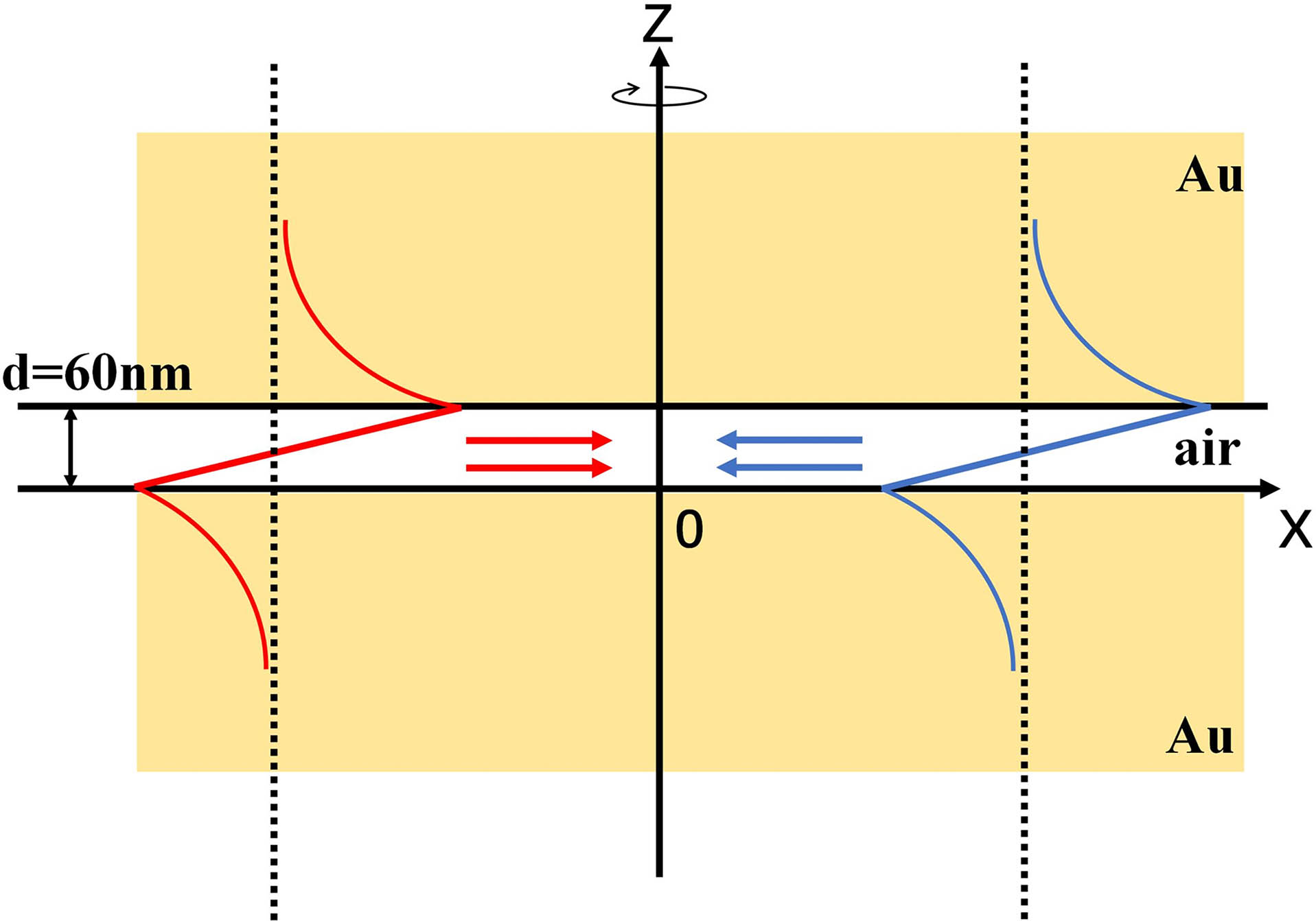
Fig. 1. Schematic diagram of MIM structure, which consists of the gold cladding layers and the air gap as the core layer. The dielectric constants of gold and air are εAu = 12.997 + 1.0341i and ε0 = 1, respectively. The thickness of the air gap is d = 60 nm. The plasmonic modes propagate towards the origin from all spatial directions to create the superchiral field.
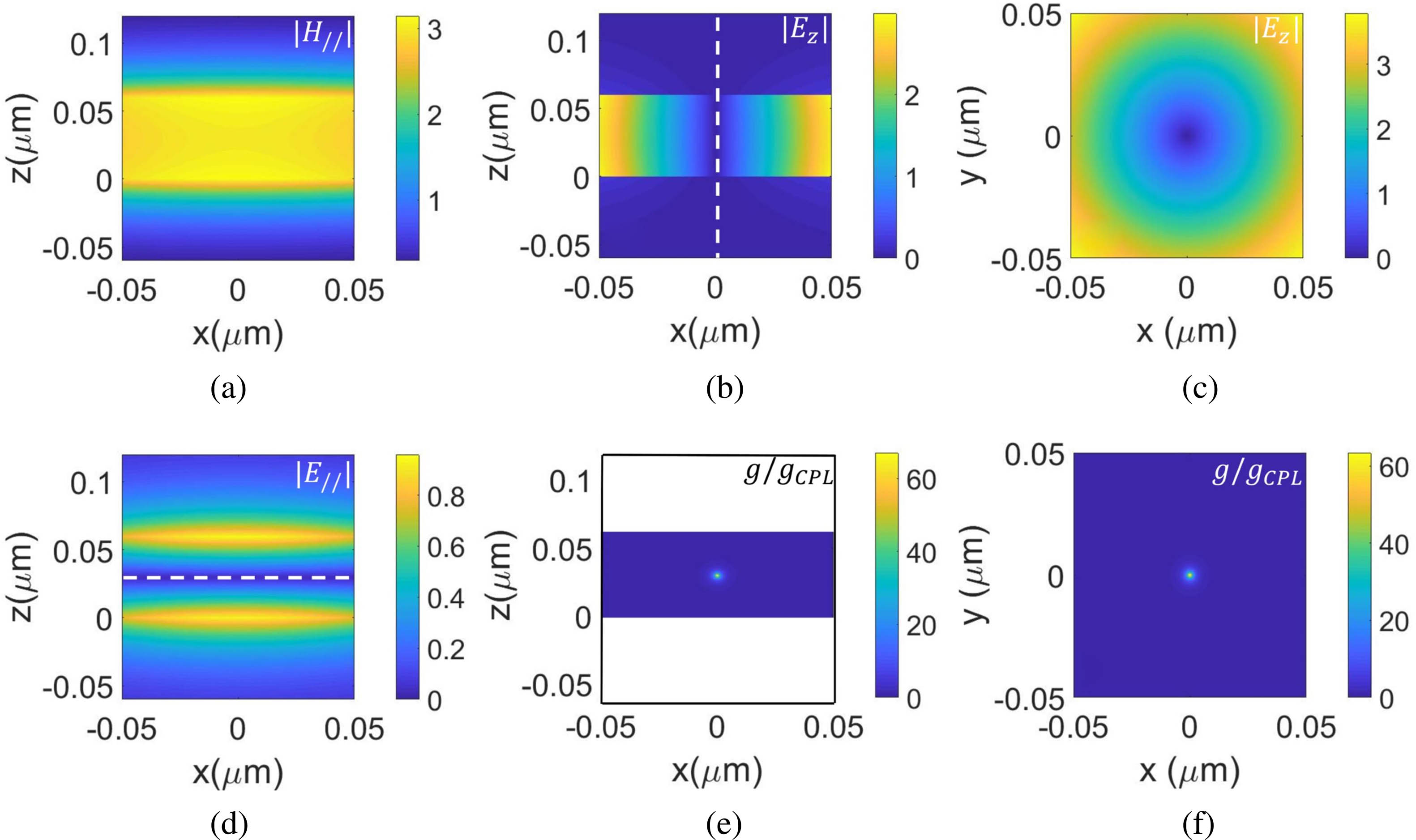
Fig. 2. Distribution of light field components and g-factor enhancement for the superchiral spot. (a) H|| in the xz plane, (b) Ez in the xz plane, (c) Ez in the xy plane, (d) E|| in the xz plane, (e) g/gCPL in the xz plane, and (f) g/gCPL in the xy plane.
Fig. 3. Schematic diagram of the focusing system to generate a superchiral spot by the plasmonic mode in the MIM structure.
Fig. 4. (a) Amplitudes of the transverse component of the magnetic field, (b), (c) amplitudes of the z component and transverse component of the electric field, (d) g-factor enhancement of the superchiral spot.
Fig. 5. (a) Positions of the superchiral spots when θ/θNA = 0.9, 0.92, 0.94, 0.96, 0.98, 0.999 for d = 60 nm. The colorbar represents the g-factor enhancement (i.e., g/gCPL). h is the z position of the superchiral spot, and d is the thickness of the air gap. (b) The relationship between the position of the superchiral field and the incident angle θ when the thickness of the air gap is 50 nm, 60 nm, 70 nm, and 80 nm.

Set citation alerts for the article
Please enter your email address
© Copyright 2018-2021 | Chinese Laser Press. All Rights Reserved 沪ICP备15018463号-20