Tao Zhuang, Haifeng Hu, Qiwen Zhan, "Generation of tunable superchiral spot in metal-insulator-metal waveguide," Chin. Opt. Lett. 21, 013601 (2023)
Copy Citation Text
The chiral feature of an optical field can be evaluated by the parameter of -factor enhancement, which is helpful to enhance chiroptic signals from a chiral dipole. In this work, the superchiral spot has been theoretically proposed in metal-insulator-metal waveguides. The -factor enhancement of the superchiral spot can be enhanced by 67-fold more than that of circularly polarized light, and the spot is confined in the deep wavelength scale along each spatial dimension. Moreover, the position of the superchiral spot can be tuned by manipulating the incident field. The tunable superchiral spot may find applications in chiral imaging and sensing.
If an object is different from its mirror image, i.e., its mirror image cannot overlap with the original object by the operations of rotation and translation, it can be called a chiral object[1]. Chirality is an important feature of three-dimensional objects and exists widely in nature. Many important biomolecules are chiral, such as amino acids, lipids, and nucleic acids. A chiral molecule and its mirror molecule with the opposite chirality are called enantiomers. How to distinguish enantiomers is important in the pharmaceutical industry, because they may have different toxicities. Since opposite enantiomers respond differently to left- and right-handed circularly polarized light (CPL), one can use chiroptical effects to realize the distinguishing characteristics. An example of these effects is circular dichroism (CD). The CD signal can be expressed as , where and are the absorption rates under the illumination of left- and right-handed CPL[2]. Because of the mismatch between the dimensions of the molecule and light wavelength, the intensity of the CD signal (i.e., the -factor) is small and difficult to measure[3]. To enhance the chiral signal, Tang and Cohen have proposed the concept of optical chirality[4], which is defined in Eq. (1): µwhere and µ are the permittivity and permeability of free space, respectively, and and are the time dependent electric and magnetic fields. For an isotropic chiral dipole, it can be proved that the -factor can be expressed as[4]µ
In Eq. (2), µ and are electric and mixed electric–magnetic dipole polarizabilities. is the time-average electric energy density of the light field. One can see that the -factor is not only determined by chiral properties of molecules [i.e., the first term of Eq. (2)], but also by the properties of the electromagnetic (EM) field [i.e., the second term of Eq. (2)]. For the CPL beam, the -factor is represented by . The enhancement of the CD signal by manipulating the optical field compared with the CPL beam can be derived as Eq. (3)[4]:
In Eq. (3), E and H are the complex amplitudes of the electric field and magnetic field. For the homogeneously polarized beam, optical chirality can reach the maximum value when the light is circularly polarized, so the ratio of cannot be larger than one. However, the superchirality condition of can be fulfilled in the local region of the inhomogeneous field[4–9]. When the left-handed and right-handed CPL beams propagate along the opposite directions, the superchiral field can be generated near the nodes of the induced standing waves[4,5]. The shape of superchiral region is a free-standing thin film, which is confined along the longitudinal direction but not along the two transverse directions. In the interference field by multiple plane waves, the periodical superchiral region can be created[6]. By tightly focusing the twisted radially polarized (RP) beam, the needle-shaped superchiral region can be generated near the focus[9]. The superchiral region is confined along the two transverse directions, but extends along the longitudinal direction. Therefore, none of the above works has realized the superchiral spot, which is confined along all the spatial directions. This aim can be achieved by the designed nanostructrues, as reported in the previous works[10–18], but the position of the superchiral spot is fixed, which introduces difficulty to immobilize chiral molecules in the superchiral region.
Sign up for Chinese Optics Letters TOC. Get the latest issue of Chinese Optics Letters delivered right to you!Sign up now
In this work, the generation method of the superchiral spot is proposed by tightly focusing the twisted RP beam in the metal-insulator-metal (MIM) waveguide. The size of the superchiral spot along each direction is much smaller than the light wavelength. The highly confined superchiral spot is constructed purely by the field of MIM waveguide mode at first. Then, the theoretical model based on the Richards–Wolf method will be employed to calculate the tightly focused beam in the MIM waveguide. In this configuration, the superchiral spot with can be obtained. Finally, the relationship between the incident condition and the position of the superchiral spot will be discussed.
2. Superchiral Field in MIM Waveguide
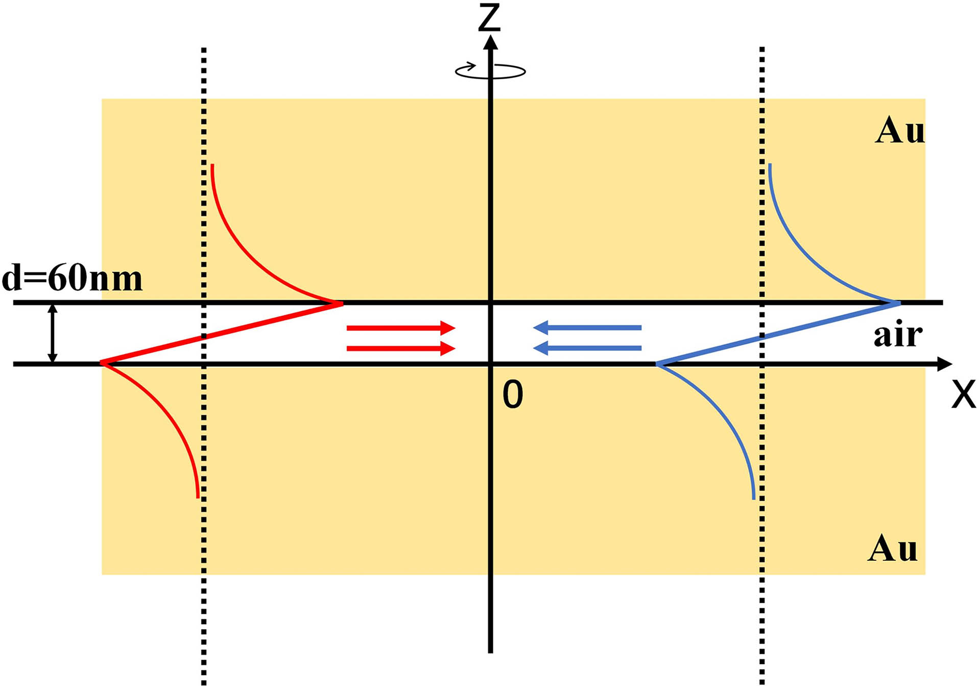
In the homogeneous EM field (i.e., plane waves), the ratio is |. However, according to the definition of the superchirality factor, the ratio of is a necessary condition to generate a superchiral EM field. This condition can be fulfilled at some localized spatial regions, where the magnetic field is enhanced and the electric field is suppressed. Consequently, the CD signal for a chiral dipole can be effectively increased under the illumination of the superchiral spot. In our previous work, the superchiral region can be realized by tightly focusing the polarization vortex beam. The superchiral region is highly confined in the transverse directions but extends along the longitudinal directions[9]. In this work, the MIM waveguide is employed to confine the light field along the axis, as shown in Fig. 1. In this structure, the air gap with the thickness of is sandwiched by two gold layers. When the wavelength is 632.8 nm, the dielectric constants of the gold layers and air gap are and . By solving the eigenequation of the MIM waveguide[19,20], one can find that only one plasmonic mode can be supported. Because of the confinement of the gold layers, the plasmonic mode propagates only along the direction in the plane. The field distribution of the plasmonic mode propagating along the direction of can be expressed as Eq. (4):
Figure 1.Schematic diagram of MIM structure, which consists of the gold cladding layers and the air gap as the core layer. The dielectric constants of gold and air are εAu = 12.997 + 1.0341i and ε0 = 1, respectively. The thickness of the air gap is d = 60 nm. The plasmonic modes propagate towards the origin from all spatial directions to create the superchiral field.
In Eq. (4), is the propagation constant of the plasmonic mode. denotes the coordinate in the plane. is the amplitude of the plasmonic mode. The angle of represents the angle between the propagation direction of the plasmonic mode and the axis. Because the mode is TM-polarized, the magnetic field only has the component along the transverse direction (i.e., 𝛟). The dependence of the vector function can be expressed as and . In this work, the synthetic field combined by the plasmonic modes propagating in the plane is considered to obtain the localized field with larger -factor than CLP. The distribution of the synthetic field near the origin can be expressed as the integration of in the range of . To make the synthetic field have chirality, the phase factor of is imposed on Eq. (4), and the amplitude of plasmonic mode is . The sign of the optical chirality is determined by the phase factor. Therefore, the synthetic field around the original point can be expressed by integration in Eq. (5):
It is convenient to calculate the synthetic field in the cylindrical coordinate of . By employing the integral formula of the Bessel function, the components of the tailored field in Eq. (5) can be simplified as the expressions in Eqs. (6): where represents the Bessel function of the first kind with the order of . The distributions of electric and magnetic fields in the MIM waveguide are shown in Fig. 2. In Fig. 2(a), the transverse component of the magnetic field has been enhanced in the air gap of the MIM waveguide. The longitudinal and transverse electrical field components (i.e., and ) of the electric field are shown in Figs. 2(b)–2(d). For the component, its amplitude distribution has axial symmetry. Along the dash line in Fig. 2(b) (i.e., ), the component of the synthetic field has been suppressed because of the destructive interference between each pair of oppositely propagating plasmonic modes. The component should be enhanced in the air gap of the MIM waveguide because of the constructive interference in the focusing field. However, according to the antisymmetric feature of of the fundamental mode in the MIM waveguide, the component is strongly confined at the interface between the air gap and gold layer, while it drops to zero at the center position of the air gap (i.e., ), whose position is marked by the white dash line in Fig. 2(d). Because the plasmonic mode is TM-polarized, the component is null in the synthetic field. Based on the analysis above, at the center of the MIM waveguide (i.e., and ), all of the electric components of the synthetic field are largely suppressed, and the magnetic field is enhanced. According to the definition of the superchirality factor in Eq. (3), the ratio of is necessary to generate a superchiral EM field. At the center of the synthetic optical field based on the plasmonic mode in the MIM waveguide , the ratio of can be much greater than . The enhancement of the -factor in the air gap is calculated to evaluate the optical chirality of the tailored field, as shown in Figs. 2(e) and 2(f). The superchiral hot spot can be found at the center of the MIM waveguide. Along each spatial dimension, the size of the superchiral region is confined in a deep subwavelength scale. The superchiral spot will be highly desired for CD imaging applications in the future. How to excite the kind of field in the MIM waveguide is important for further studying the features of the localized superchiral field. In this work, a tightly focused system is theoretically designed to generate the proposed superchiral field.
Figure 2.Distribution of light field components and g-factor enhancement for the superchiral spot. (a) H|| in the xz plane, (b) Ez in the xz plane, (c) Ez in the xy plane, (d) E|| in the xz plane, (e) g/gCPL in the xz plane, and (f) g/gCPL in the xy plane.
The theoretically designed system has been shown in Fig. 3. The RP beam is employed as the incident field. After passing through the spiral phase plate (SPP), the wavefront of the RP beam has been twisted by multiplying the helical phase factor of . The chirality of the twisted wavefront is determined by the topological handedness of the SPP structure. Then, the twisted RP beam is focused by the oil-immersed lens. Before the focusing lens, the ring aperture is employed to filter the twisted RP beam. For the high numerical aperture (NA) system, the focusing field can be calculated by the Richards–Wolf method[21–23]. The focusing field in free space can be decomposed by the plane waves with different propagating directions . In this work, the four-layer model is employed to analyze the interaction between the focusing field and the MIM waveguide, as shown in Fig. 3. The first layer is the oil with high refractive index (). The second layer is the gold film. To couple the light into the MIM waveguide, the thickness of the gold layer is only 40 nm. The third layer is the air gap with the thickness of 60 nm, which is the same as the previous model in Fig. (1). The last layer is the thick gold layer deposited on the substrate. When the thickness of the last gold layer is large enough, the influence of the glass substrate can be neglected. The two gold layers and the air gap can be considered as the MIM waveguide. The light field distribution in the four-layer structure can be expressed as
Figure 3.Schematic diagram of the focusing system to generate a superchiral spot by the plasmonic mode in the MIM structure.
In Eq. (7), the superscript () represents the number of each layer. The interface between layer and layer is at the position of . In cylindrical coordinates, the incident field of can be calculated by the Richards–Wolf method[21–23] as Eq. (8):
In Eq. (8), . is a constant related to the focal length and the wavelength, is the wavenumber in the oil layer. is the corresponding wave impedance. In this work, , which depends on the handedness of the SPP. The apodization function of the lens can be expressed by Eq. (9): where , , and . is the focal length of the lens. The RP beam is considered in the numerical model, so only the p-polarized plane waves are included in the focusing field. The integral range can be determined by the aperture zone selected by the ring aperture before the focusing lens. To analyze the focusing field in the MIM waveguide, the transmission and reflection by the interface of the four-layer model should be considered. In the first layer (i.e., incident region), the light field is the sum of the incident field and reflection field. In the last layer (transmission region), the light field is only the transmission field. In the intermediate layer (i.e., , 3), there are both the forward-propagating waves and backward-propagating waves . It should be noticed that the transmission and refection coefficients depend on the angle of . Therefore, the plane waves with different should be considered separately. The numerical model can be easily expanded to the complex structure with more layers by employing the transfer-matrix method[24].
To generate the surface plasmon wave, the incident angle should be greater than the critical angle, and then the evanescent wave can be generated to realize phase matching with the surface plasma wave. Therefore, the range of incident angle should be , which is limited by the NA and the critical angle .
Sign up for Chinese Optics Letters TOC. Get the latest issue of Chinese Optics Letters delivered right to you!Sign up now
When the width of the ring aperture is much smaller than the diameter of the lens, the focused field becomes the Bessel beam approximately. Therefore, to simplify the analysis, an individual incident angle is considered. When the incident angle is , the amplitudes of all components in the focus field can be shown as in Figs. 4(a)–4(c). The distribution of the light field in the MIM structure is similar to the results in Fig. 2. As shown in Fig. 4(b), the component in the air gap is largely enhanced at the interface between the air gap and the upper gold layer but suppressed inside the air gap. The distribution of -factor enhancement is shown in Fig. 4(d). The definition of the -factor is not applicable in metal materials, which has large dispersion and high loss[25]. Therefore, the distribution of the -factor is only calculated in the air gap. The width of the superchiral spot is 2.6 nm, and the height is 4.4 nm. Both sizes are in the deep subwavelength scale. By comparing Figs. 4(b) and 4(d), the positions of the minimum transverse electric field and the superchiral spot are the same (i.e., ). From the analysis above, the components and are tailored by different mechanisms. The component is suppressed on the axis due to the twisted wavefront carried by the incident RP beam from the far field. The component drops to zero value at because of the near-field MIM structure. The position of the superchiral spot is not at the center of the air gap as demonstrated in Fig. 2. It means there are also other evanescent field components in the air gap except the plasmonic mode. Therefore, the position of the superchiral spot is closely related to the incident focusing field. By laterally moving the focusing light field, the position of the superchiral spot can be tuned along the and directions. Next, we will demonstrate the position tunability of the superchiral spot along the direction.
Figure 4.(a) Amplitudes of the transverse component of the magnetic field, (b), (c) amplitudes of the z component and transverse component of the electric field, (d) g-factor enhancement of the superchiral spot.
The influence of incident angle on the superchiral spot is investigated. When the incident angle is , , , , , and , the positions of the superchiral spot are as shown in Fig. 5(a). The thickness of the air gap is . It can be seen that the superchiral spot moves along the direction when the angle of is increased. At the same time, both the shape and enhancement factor of the superchiral spot remain almost unchanged. The chiral signal can be enhanced by 67-fold more than that by illumination of CPL. To further study the relationship between the position of superchiral spot and , the thickness of the air gap is varied from 50 nm to 80 nm, as shown in Fig. 5(b). One can see that when the thickness of the air gap is 60 nm, the tunable range of superchiral spot along the axis is from 0 nm to 18 nm. When , the width of the tunable range is reduced. When increases from 60 nm to 80 nm, the width of the tunable range is nearly unchanged in the range of , but the position is shifted along the axis. The tuning range can be further extended by increasing the NA of the focusing lens. In the tight focusing system, when the incident angle is strongly confined by the ring aperture, the Bessel beam can be generated approximately. For example, when the incident angle is in the range of , the superchiral hot spot can also be generated. By using the sine condition, which is related to the stigmatic imaging process, the lateral position of the incident ray can be expressed as [26]. The transmission efficiency of the incident beam through the ring aperture is estimated to be 1.78%. Therefore, the superchiral field can be generated by a high power laser with the output of the fundamental transverse mode. For the fluorescent chiral molecules, the absorption power can be evaluated by the intensity of fluorescence. Therefore, the proposed superchiral field can be employed in the method of fluorescence-detected CD (FDCD) to probe the chirality of molecules[5].
Figure 5.(a) Positions of the superchiral spots when θ/θNA = 0.9, 0.92, 0.94, 0.96, 0.98, 0.999 for d = 60 nm. The colorbar represents the g-factor enhancement (i.e., g/gCPL). h is the z position of the superchiral spot, and d is the thickness of the air gap. (b) The relationship between the position of the superchiral field and the incident angle θ when the thickness of the air gap is 50 nm, 60 nm, 70 nm, and 80 nm.
In conclusion, we proposed a theoretical design to generate a superchiral spot by tightly focusing twisted RP beams in the MIM structure. The superchiral spot is confined within deep subwavelength scales along all spatial directions. The -factor at the superchiral spot is enhanced by 67-fold more than that in the CPL field. Moreover, the position of the superchiral spot can be linearly adjusted along the direction when the angle of is increased. In the actual measurement, the influence of the perturbed environment is inevitable[27], which may reduce the signal-to-noise ratio of the chirality measurement. The optical confocal method can be used to alleviate the problem. This kind of superchiral field will have great potential in CD measurements of sparse chiral objects, especially for recognizing the chirality of a single molecule.
References
[1] L. D. Barron. Molecular Light Scattering and Optical Activity(2004).
[2] Y. Inoue, V. Ramamurthy. Chiral Photochemistry(2004).
[3] J. Mun, M. Kim, Y. Yang, T. Badloe, J. Ni, Y. Chen, C. W. Qiu, J. Rho. Electromagnetic chirality: from fundamentals to nontraditional chiroptical phenomena. Light Sci. Appl., 9, 139(2020).
[4] Y. Tang, A. E. Cohen. Optical chirality and its interaction with matter. Phys. Rev. Lett., 104, 163901(2010).
[5] Y. Tang, A. E. Cohen. Enhanced enantioselectivity in excitation of chiral molecules by superchiral light. Science, 332, 333(2011).
[6] K. C. van Kruining, R. P. Cameron, J. B. Götte. Super- positions of up to six plane waves without electric-field interference. Optica, 5, 1091(2018).
[7] N. Yang, A. E. Cohen. Local geometry of electromagnetic fields and its role in molecular multipole transitions. J. Phys. Chem. B, 115, 5304(2011).
[8] C. Rosales-Guzmán, K. Volke-Sepulveda, J. P. Torres. Light with enhanced optical chirality. Opt. Lett., 37, 3486(2012).
[9] H. Hu, Q. Gan, Q. Zhan. Generation of a nondiffracting superchiral optical needle for circular dichroism imaging of sparse subdiffraction objects. Phys. Rev. Lett., 122, 223901(2019).
[10] A. Vazquez-Guardado, D. Chanda. Superchiral light generation on degenerate achiral surfaces. Phys. Rev. Lett., 120, 137601(2018).
[11] K. Yao, Y. M. Liu. Enhancing circular dichroism by chiral hotspots in silicon nanocube dimers. Nanoscale, 10, 8779(2018).
[12] G. Rui, H. Hu, Q. Zhan, Q. Gan. Symmetric meta-absorber-induced superchirality. Adv. Opt. Mater., 7, 1901038(2019).
[13] J. Mun, J. Rho. Importance of higher-order multipole transitions on chiral nearfield interactions. Nanophotonics, 8, 941(2019).
[14] J. Mun, S. So, J. Jang, J. Rho. Describing meta-atoms using the exact higher-order polarizability tensors. ACS Photonics, 7, 1153(2020).
[15] M. Kim, J. Rho. Plasmonic-enhanced chirality examined by generalized wavenumber eigenvalue simulation. Opt. Express, 26, 014051(2018).
[16] J. Mun, J. Rho. Surface-enhanced circular dichroism by multipolar radiative coupling. Opt. Lett., 43, 002856(2018).
[17] H. Hu, Q. Gan, Q. Zhan. Achieving maximum scattering circular dichroism through the excitation of anapole states within chiral Mie nanospheres. Phys. Rev. B, 105, 245412(2022).
[18] G. R. Guzman, K. V. Sepulveda, J. P. Torres. Light with enhanced optical chirality. Opt. Lett., 37, 3486(2012).
[19] H. Wang, J. Zheng, Y. Fu, C. Wang, X. Huang, Z. Ye, L. Qian. Multichannel high extinction ratio polarized beam splitters based on metasurfaces. Chin. Opt. Lett., 17, 052303(2019).
[20] S. A. Maier. Plasmonics: Fundamentals and Applications(2007).
[21] K. Youngworth, T. Brown. Focusing of high numerical aperture cylindrical-vector beams. Opt. Express, 7, 77(2000).
[22] J. Kim, Y. Wang, X. Zhang. Calculation of vectorial diffraction in optical systems. J. Opt. Soc. Am. A, 35, 526(2018).
[23] Q. Zhan. Cylindrical vector beams: from mathematical concepts to applications. Adv. Opt. Photonics, 1, 1(2009).
[24] C. L. Mitsas, D. I. Siapkas. Generalized matrix method for analysis of coherent and incoherent reflectance and transmittance of multilayer structures with rough surfaces, interfaces, and finite substrates. Appl. Opt., 34, 1678(1995).
[25] J. E. Vázquez-Lozano, A. Martínez. Optical chirality in dispersive and lossy media. Phys. Rev. Lett., 121, 043901(2018).
[26] M. Born, E. Wolf. Principles of Optics(1999).
[27] S. Lee, S. J. Yoo, Q. H. Park. Microscopic origin of surface-enhanced circular dichroism. ACS Photonics, 4, 2047(2017).