• Photonics Research
  • Vol. 11, Issue 2, 329 (2023)
Penghui Xia1, Hui Yu1、2、*, Mingxiang Yang3, Naidi Cui3, Haijun Liao3, Qiang Zhang2, Zhilei Fu1, Qikai Huang1, Nannan Ning1, Zhujun Wei1, Xiaoqing Jiang1, and Jianyi Yang1
Author Affiliations
  • 1Institute of Integrated Microelectronic systems, College of Information Science and Electronic Engineering, Zhejiang University, Hangzhou 310027, China
  • 2Zhejiang Lab, Hangzhou 310027, China
  • 3United Microelectronics Center, Chongqing 404100, China
  • show less
    DOI: 10.1364/PRJ.473778 Cite this Article Set citation alerts
    Penghui Xia, Hui Yu, Mingxiang Yang, Naidi Cui, Haijun Liao, Qiang Zhang, Zhilei Fu, Qikai Huang, Nannan Ning, Zhujun Wei, Xiaoqing Jiang, Jianyi Yang. High sideband suppression silicon single sideband modulator integrated with a radio frequency branch line coupler[J]. Photonics Research, 2023, 11(2): 329 Copy Citation Text show less
    (a) Microphotograph of the silicon OSSB modulation chip consisting of an RF BLC and a DP-MZM with adjustable optical power splitting ratio. (b) Cross section schematic diagram of the device, which includes the CPW with floating strips, carrier-depletion-based phase shifter, TiN heater, and grating coupler (GC). (c) Floorplan of the silicon OSSB modulation chip. (d) Three-dimensional (3D) diagram of the CPW transmission line with floating strips to suppress the slot-line mode. (e) 3D diagram of the reciprocal transition structure between CPW and CPS electrodes. (f) 3D diagram of the single-drive series push–pull MZM integrated with an inductive line. (g) Cross-sectional schematic diagram of the phase shifter.
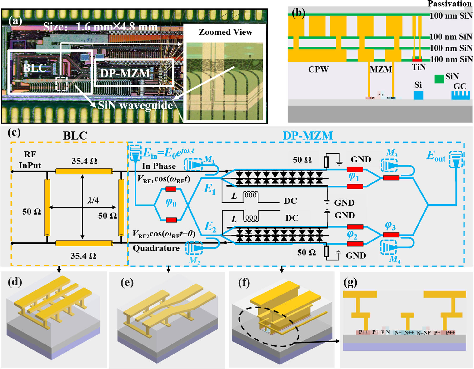
    Fig. 1. (a) Microphotograph of the silicon OSSB modulation chip consisting of an RF BLC and a DP-MZM with adjustable optical power splitting ratio. (b) Cross section schematic diagram of the device, which includes the CPW with floating strips, carrier-depletion-based phase shifter, TiN heater, and grating coupler (GC). (c) Floorplan of the silicon OSSB modulation chip. (d) Three-dimensional (3D) diagram of the CPW transmission line with floating strips to suppress the slot-line mode. (e) 3D diagram of the reciprocal transition structure between CPW and CPS electrodes. (f) 3D diagram of the single-drive series push–pull MZM integrated with an inductive line. (g) Cross-sectional schematic diagram of the phase shifter.
    Power attenuation of the retained sideband versus the amplitude imbalance and the phase difference between the RF outputs of I and Q ports.
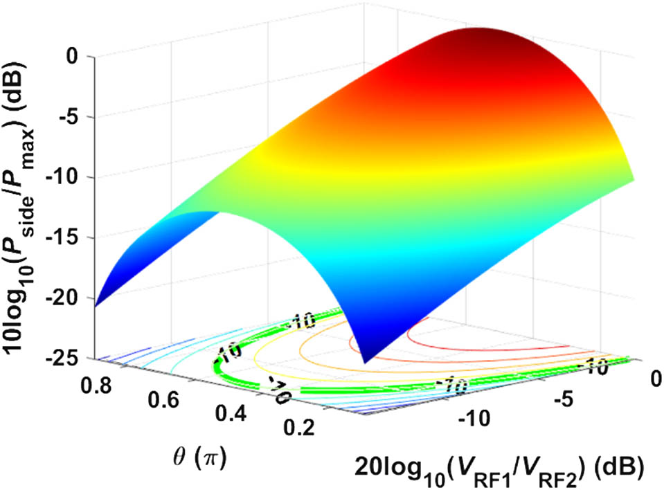
    Fig. 2. Power attenuation of the retained sideband versus the amplitude imbalance and the phase difference between the RF outputs of I and Q ports.
    (a) Optical transmission spectra of the imbalanced reference MZM under different reversed bias voltages. The coupling losses of two grating couplers have been normalized. (b) Measured EE S11 and EO S21 parameters of the MZM. (c) Measured EO crosstalk between the two sub-MZMs with a pitch of 300 μm.
    Fig. 3. (a) Optical transmission spectra of the imbalanced reference MZM under different reversed bias voltages. The coupling losses of two grating couplers have been normalized. (b) Measured EE S11 and EO S21 parameters of the MZM. (c) Measured EO crosstalk between the two sub-MZMs with a pitch of 300 μm.
    (a) Simulated and (b) measured RF output characteristics of the I and Q ports of the BLC.
    Fig. 4. (a) Simulated and (b) measured RF output characteristics of the I and Q ports of the BLC.
    Output spectra of the OSSB modulator with a resolution of 0.02 nm in (a) the FC-OSSB mode and (b) the SC-OSSB mode. (c) Practical values of β to enable high SSRs at different frequencies.
    Fig. 5. Output spectra of the OSSB modulator with a resolution of 0.02 nm in (a) the FC-OSSB mode and (b) the SC-OSSB mode. (c) Practical values of β to enable high SSRs at different frequencies.
    Penghui Xia, Hui Yu, Mingxiang Yang, Naidi Cui, Haijun Liao, Qiang Zhang, Zhilei Fu, Qikai Huang, Nannan Ning, Zhujun Wei, Xiaoqing Jiang, Jianyi Yang. High sideband suppression silicon single sideband modulator integrated with a radio frequency branch line coupler[J]. Photonics Research, 2023, 11(2): 329
    Download Citation