
Wenwei Ye, Tianfu Zhou, Jinxuan Huang, Feng Lin. Design of Dual-Vision Double Telecentric Optical System Based on Machine Vision[J]. Laser & Optoelectronics Progress, 2020, 57(1): 012202
- Laser & Optoelectronics Progress
- Vol. 57, Issue 1, 012202 (2020)
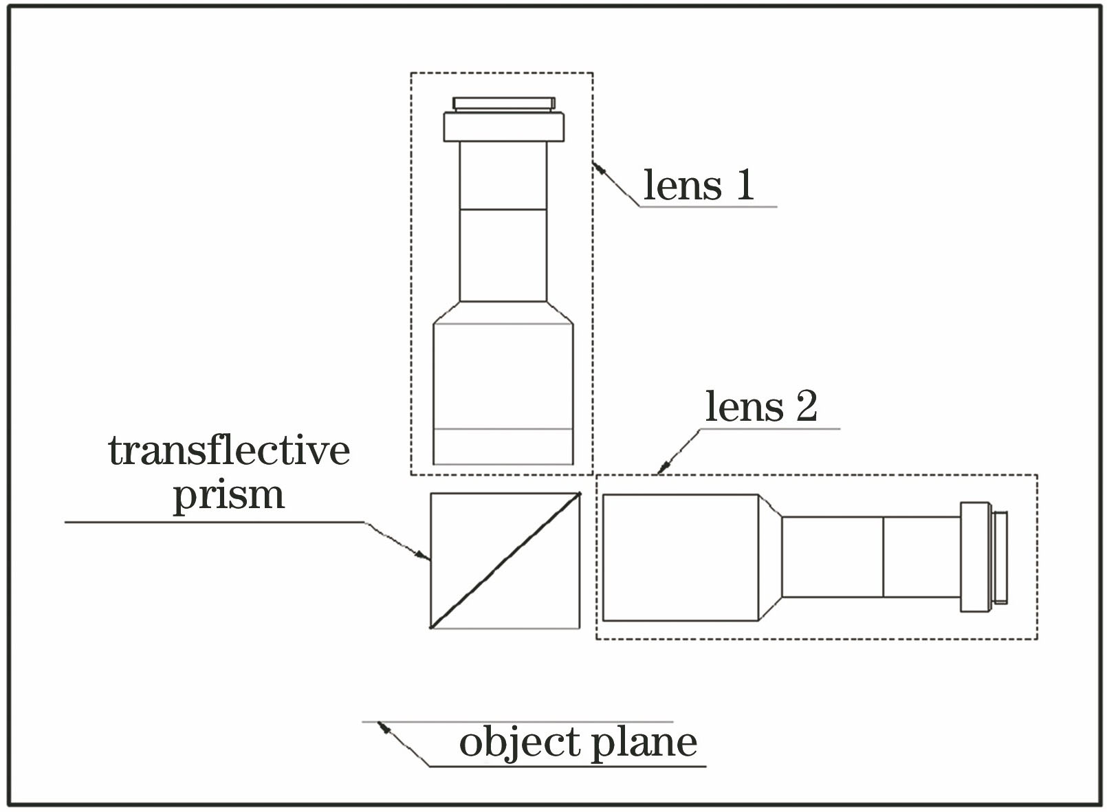
Fig. 1. Diagram of common solution
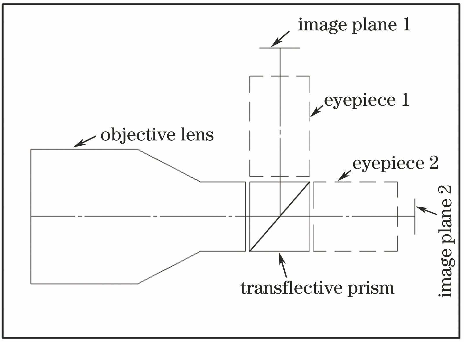
Fig. 2. Diagram of solution in this paper
Fig. 3. System initial structural diagram
Fig. 4. Outline drawing of optical system
Fig. 5. MTF plots when magnification is -0.1375
Fig. 6. MTF plots when magnification is -0.275
Fig. 7. System distortion diagram when magnification is -0.1375
Fig. 8. System distortion diagram when magnification is -0.275
Fig. 9. Spot diagrams when magnification is -0.1375
Fig. 10. Spot diagrams when magnification is -0.275
Fig. 11. Monte Carlo simulation results. (a) Most influential tolerance and its position in structure 1 (magnification is -0.1375); (b) most influential tolerance and its position in structure 2 (magnification is -0.275); (c) MTF curves obtained by Monte Carlo simulation of structure 1 (magnification is -0.1375); (d) MTF curves obtained by Monte Carlo simulation of structure 2 (magnification is -0.275); (e) distortion curves obtained by Monte Carlo simulation of structure 1 (magnification is -0.1375); (f
|
Table 1. Imaging chip parameters
|
Table 2. System design parameters
| |||||||||||||||||||
Table 3. System telecentricity
|
Table 4. Tolerance range of optical system

Set citation alerts for the article
Please enter your email address
© Copyright 2018-2021 | Chinese Laser Press. All Rights Reserved 沪ICP备15018463号-20