• Laser & Optoelectronics Progress
  • Vol. 58, Issue 6, 628004 (2021)
Zhan Chao1, Peng Xiaoyong2, and Li Yang2,*
Author Affiliations
  • 1Zhuhai Branch, Guangdong Institute of Special Equipment Inspection and Research, Zhuhai, Guangdong 519002, China
  • 2School of Mechanical Engineering, Zhengzhou University, Zhengzhou, Henan 450001, China
  • show less
    DOI: 10.3788/LOP202158.0628004 Cite this Article Set citation alerts
    Zhan Chao, Peng Xiaoyong, Li Yang. Nondestructive Testing Cracks on Inner Surface of Thick Pipes by Laser Ultrasonic Visualization[J]. Laser & Optoelectronics Progress, 2021, 58(6): 628004 Copy Citation Text show less
    Finite element model of inner wall defect of thick pipe
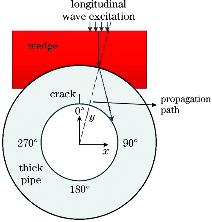
    Fig. 1. Finite element model of inner wall defect of thick pipe
    Images of ultrasonic transmission at different moments. (a) 9×10⁻⁶ s; (b) 14×10-6 s; (c) 18×10-6 s; (d) 24×10-6 s
    Fig. 2. Images of ultrasonic transmission at different moments. (a) 9×10⁻⁶ s; (b) 14×10-6 s; (c) 18×10-6 s; (d) 24×10-6 s
    Laser ultrasonic detection device
    Fig. 3. Laser ultrasonic detection device
    Distribution of sound field in different propagation process. (a) Piezoelectric probe excites ultrasonic longitudinal wave on thick-walled tube; (b) longitudinal wave is reflected when it encounters inner wall; (c) creeping wave is formed by mode conversion of longitudinal wave on internal wall; (d) creeping wave propagates along inner wall
    Fig. 4. Distribution of sound field in different propagation process. (a) Piezoelectric probe excites ultrasonic longitudinal wave on thick-walled tube; (b) longitudinal wave is reflected when it encounters inner wall; (c) creeping wave is formed by mode conversion of longitudinal wave on internal wall; (d) creeping wave propagates along inner wall
    Detection device of creeping wave probe
    Fig. 5. Detection device of creeping wave probe
    Detection signal of the trial-produced probe. (a) No load of probe; (b) probe is attached to non-defective steel tube; (c) probe is directly above crack; (d) probe and crack are at position of 90°; (e) probe and crack are at position of 180°; (f) probe and crack are at position of 270°
    Fig. 6. Detection signal of the trial-produced probe. (a) No load of probe; (b) probe is attached to non-defective steel tube; (c) probe is directly above crack; (d) probe and crack are at position of 90°; (e) probe and crack are at position of 180°; (f) probe and crack are at position of 270°
    MaterialElastic modulus(E) /GPaPoisson ratio(ν)Density(ρ) / (kg·m-3)
    Polymethyl methacrylate2.330.371190
    304 stainless steel193.000.298000
    Table 1. Material parameters of finite element simulation
    Zhan Chao, Peng Xiaoyong, Li Yang. Nondestructive Testing Cracks on Inner Surface of Thick Pipes by Laser Ultrasonic Visualization[J]. Laser & Optoelectronics Progress, 2021, 58(6): 628004
    Download Citation