• Chinese Optics Letters
  • Vol. 19, Issue 7, 071403 (2021)
Cheng Yin1, Xuefen Kan1, Kun Guo2, Tao Wang2, Jiangming Xu2, Qingbang Han1, Jian Wu2、*, and Zhuangqi Cao3
Author Affiliations
  • 1College of Internet of Things Engineering, Hohai University, Changzhou 213022, China
  • 2College of Advanced Interdisciplinary Studies, National University of Defense Technology, Changsha 410073, China
  • 3Department of Physics and Astronomy, Shanghai Jiao Tong University, Shanghai 200240, China
  • show less
    DOI: 10.3788/COL202119.071403 Cite this Article Set citation alerts
    Cheng Yin, Xuefen Kan, Kun Guo, Tao Wang, Jiangming Xu, Qingbang Han, Jian Wu, Zhuangqi Cao. Highly twisted M-line of a vortex beam due to the coupling of ultrahigh-order modes[J]. Chinese Optics Letters, 2021, 19(7): 071403 Copy Citation Text show less
    Refraction of an optical VB by an SMCW chip and the E-field distribution of an oscillating UOM at resonance (red line).
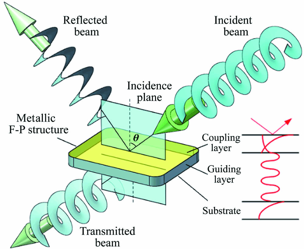
    Fig. 1. Refraction of an optical VB by an SMCW chip and the E-field distribution of an oscillating UOM at resonance (red line).
    (a) Optical field of the incident beam generated by a spiral phase plate with l = 1. (b), (c), and (d) Optical field of the reflected beam at 9.42, 9.50, and 9.52 deg, respectively. The intensity is normalized to the maximum of the incident light spot.
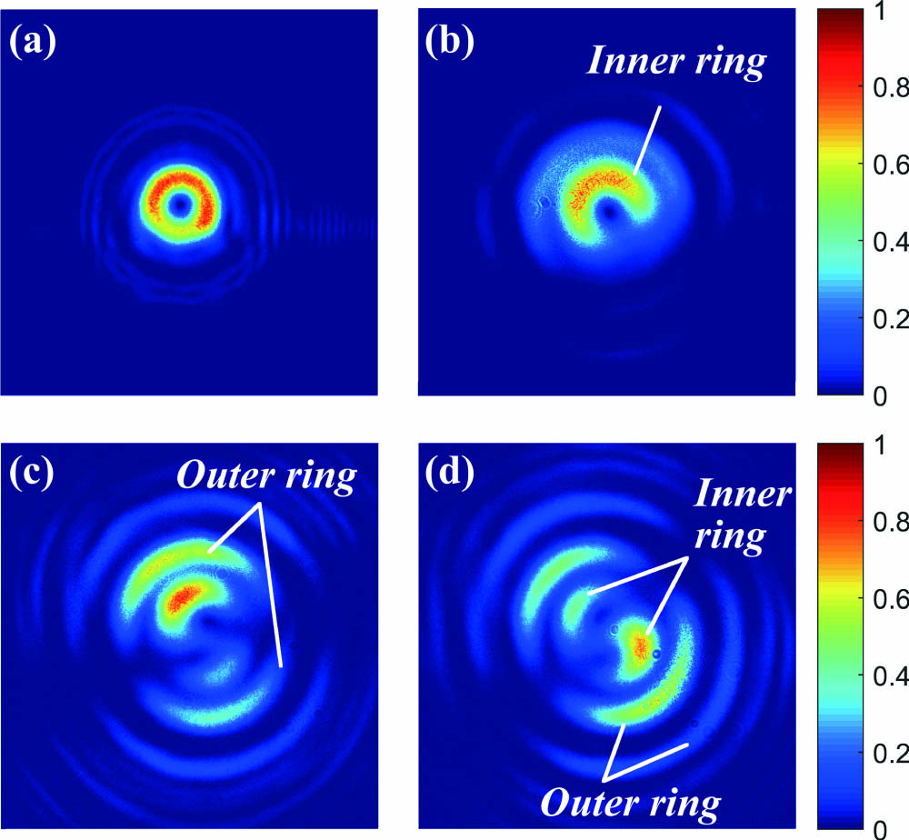
    Fig. 2. (a) Optical field of the incident beam generated by a spiral phase plate with l = 1. (b), (c), and (d) Optical field of the reflected beam at 9.42, 9.50, and 9.52 deg, respectively. The intensity is normalized to the maximum of the incident light spot.
    (Top) Experimentally measured reflectivity of a VB reflected by the SMCW chip; (bottom) numerically simulated reflectivity of a planar wave model via the transfer matrix method. The permittivity of silver is based on the Drude model εAg = −13.9235 + 0.7233i, and the permittivity of the guiding layer is 2.25.
    Fig. 3. (Top) Experimentally measured reflectivity of a VB reflected by the SMCW chip; (bottom) numerically simulated reflectivity of a planar wave model via the transfer matrix method. The permittivity of silver is based on the Drude model εAg = −13.9235 + 0.7233i, and the permittivity of the guiding layer is 2.25.
    Evolution of the M-line in a reflected Gaussian beam under the same experimental conditions. The coupling angle of the resonant dip is around 9.13 deg. The intensity is normalized to the maximum of the reflected light spot in (b).
    Fig. 4. Evolution of the M-line in a reflected Gaussian beam under the same experimental conditions. The coupling angle of the resonant dip is around 9.13 deg. The intensity is normalized to the maximum of the reflected light spot in (b).
    Reflection spectra of a prism-coupled SMCW chip as a function of film thickness and incident angle. θc is the critical angle for total reflection of the guiding layer.
    Fig. 5. Reflection spectra of a prism-coupled SMCW chip as a function of film thickness and incident angle. θc is the critical angle for total reflection of the guiding layer.
    (a) Phase structure and related energy flux S⇀ distribution (black arrow) in the beam cross sections at different propagation distances. (b) The distribution of the energy flux vector (red arrow) at a tilted cross section (blue circle) due to a nonzero incident angle θ.
    Fig. 6. (a) Phase structure and related energy flux S distribution (black arrow) in the beam cross sections at different propagation distances. (b) The distribution of the energy flux vector (red arrow) at a tilted cross section (blue circle) due to a nonzero incident angle θ.
    Simulated inner ring and the M-line of the reflected VB (l = 1) near a resonance, where the parameters are the same as those used in Fig. 3. The beam waist is 0.5 mm, and the propagation distance is z = 50 cm.
    Fig. 7. Simulated inner ring and the M-line of the reflected VB (l = 1) near a resonance, where the parameters are the same as those used in Fig. 3. The beam waist is 0.5 mm, and the propagation distance is z = 50 cm.
    (a), (d) Intensities and (b), (e) phase structures of the reflected beams with different topological charge l; (c), (f) the phase structures of the incident beams are also plotted for comparison. The incident angle is θ = 30 deg, and the rest parameters are the same as those used in Fig. 7.
    Fig. 8. (a), (d) Intensities and (b), (e) phase structures of the reflected beams with different topological charge l; (c), (f) the phase structures of the incident beams are also plotted for comparison. The incident angle is θ = 30 deg, and the rest parameters are the same as those used in Fig. 7.
    Cheng Yin, Xuefen Kan, Kun Guo, Tao Wang, Jiangming Xu, Qingbang Han, Jian Wu, Zhuangqi Cao. Highly twisted M-line of a vortex beam due to the coupling of ultrahigh-order modes[J]. Chinese Optics Letters, 2021, 19(7): 071403
    Download Citation