
Ran He, Liang Zhu, Junfa Dong, Zhenzhong Xiao, Yuming Dong. Modeling and Simulation of LiDAR Based on Single-Photon Avalanche Diode[J]. Laser & Optoelectronics Progress, 2024, 61(10): 1028003
- Laser & Optoelectronics Progress
- Vol. 61, Issue 10, 1028003 (2024)
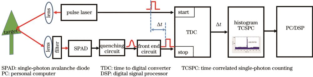
Fig. 1. Schematic diagram of LiDAR ranging based on SPAD

Fig. 2. Receiving and emitting model for LiDAR
Fig. 3. Photon response diagram in passive reset circuit and active reset circuit
Fig. 4. Signal response diagram of single-event first-photon TDC and multi-event TDC
Fig. 5. Schematic diagram for LiDAR modeling process based on SPAD
Fig. 6. Simulation histograms of passive reset mode and active reset mode quenching circuits under the condition of the time of flight of 20 ns and the ambient light of 50×103 lx. (a) Passive reset circuit histogram with target reflectivity of 10%; (b) active reset circuit histogram with target reflectivity of 10%; (c) passive reset circuit histogram with target reflectivity of 50%; (d) active reset circuit histogram with target reflectivity of 50%
Fig. 7. Success rates of different TOFs for two types of circuits under ambient light of 50×103 lx. (a) Target reflectivity is 10%; (b) target reflectivity is 50%
Fig. 8. Histograms of single-event first-photon TDC and multi-event TDC under different conditions. (a) Histogram of single-event first-photon TDC under the ambient light of 50×103 lx; (b) histogram of multi-event TDC under the ambient light of 50×103 lx; (c) histogram of single-event first-photon TDC under the ambient light of 100×103 lx; (d) histogram of multi-event TDC under the ambient light of 100×103 lx
Fig. 9. Success rates of single-event first-photon TDC and multi-event TDC under the target reflectivity of 10%. (a) Ambient light of 50×103 lx; (b) ambient light of 100×103 lx
Fig. 10. Histograms of four combined circuit architectures. (a) Passive reset circuit+single-event first-photon TDC; (b) active reset circuit+single-event first-photon TDC; (c) passive reset circuit+multi-event TDC; (d) active reset circuit+multi-event TDC
Fig. 11. Success rates of four combination circuits under the ambient light of 50×103 lx and the target reflectivity of 50%
|
Table 1. Key parameters of each module of the LiDAR system

Set citation alerts for the article
Please enter your email address
© Copyright 2018-2021 | Chinese Laser Press. All Rights Reserved 沪ICP备15018463号-20