K. D. Leake1,*, A. R. Hawkins2, and H. Schmidt1
Abstract
We analyze the properties of a dual-beamtrap of orthogonally intersecting beams in the geometrical optics regime. We derive analytical expressions for the trapping location and stability criteria for trapping a microparticle with uncollimated Gaussian beams. An upper limit for the beam waist is found. Optical forces and particle trajectories are calculated numerically for the realistic case of a microparticle in intersecting liquid-core waveguides.1. INTRODUCTION
The ability to control the external degrees of freedom of a massive particle with massless photons in a beam of light remains one of the most fascinating concepts in optical physics. The field was initiated by Ashkin’s seminal proposal on all-optical trapping of neutral particles in a dual-beam trap (DBT) of opposing laser beams [1]. Subsequently, a single-beam optical trap created by a tightly focused beam was demonstrated using both microspheres and atoms [2,3]. Using single-beam “laser tweezers” for manipulating individual biological particles is now standard practice in countless laboratories, where biological studies represent the bulk of optical trapping applications [4–6]. In addition to tweezers, a number of other trapping methods have been developed that involve phase and amplitude shaping of an optical field [7–9] or rely on the combination of light with other forces, including mechanical [10], electrical [11], and magnetic [12]—all expanding the concept of the single-beam trap (SBT). A large body of literature on both theory and experiments of these optical traps over a wide range of particle sizes and materials exists [13,14].
Most recently, an increasing trend to implement particle traps in integrated photonic structures has emerged [15–20]. While photonic integration is attractive due to the potential of building compact and easy-to-use devices for particle manipulation, the implementation of the standard single-beam tweezer trap is extremely challenging because the creation of the required large numerical apertures is concomitant with significant propagation losses in waveguides whose dimensions do not change adiabatically. The ideal photonically integrated all-optical trap would therefore rely on collimated beams with constant beam (“mode”) dimensions. One example of such a trap is the loss-based DBT that uses counterpropagating beams in the presence of waveguide loss [15]. Another attractive alternative is to use two crossed beams. Such a geometry has been demonstrated in the Rayleigh regime for the evaporative cooling of atoms [21]. Several groups have used this orthogonal geometry for experiments on atoms including cooling and Bose–Einstein condensate formation [22,23]. However, many applications in biology and related fields utilize dielectric beads and cells of micrometer-scale dimensions. Therefore, we analyze an all-optical trap using orthogonally intersecting beams in the geometrical optics regime. Expressions for the trapping location and stability criteria that qualitatively differ from the atom trapping limit are derived analytically. Simulations of particle capture and trapping under realistic conditions of a micrometer sized particle in intersecting liquid-core waveguides show that the orthogonal beam trap (OBT) is ideal for implementation in microfluidic channels without the need for strongly focused or diverging beams.
2. THEORY
The physical principle responsible for achieving trapping in all three all-optical traps is shown in Fig. 1. In the original Ashkin traps [Figs. 1(a) and 1(b)], trapping along the direction is accomplished by balancing scattering and gradient forces (SBT) or opposing scattering forces (DBT). Confinement in the other dimensions is provided by gradient forces. In the OBT, however, trapping in both the and directions is achieved by balancing the gradient force from one beam with the scattering force from the other beam. While a first look at the beam geometry might lead us to expect the particle to be pushed along a diagonal trajectory, closer inspection reveals that as a particle is pushed out of the center of Beam 2 by Beam 1 along the direction, a restoring gradient force starts building up that reduces the net force. Trapping may occur at the point where the two forces balance each other. This situation is qualitatively illustrated in Fig. 1(d). Although the scattering force from Beam 1 has a Gaussian shape along the direction [see Fig. 1(c)], for any given position its value is constant. The vector sum of and creates a potential along the direction that can be sufficiently deep to trap a particle [see Fig. 4(a) for a specific example]. A similar analysis is valid for the direction with the roles of Beams 1 and 2 reversed.
Sign up for Photonics Research TOC. Get the latest issue of Photonics Research delivered right to you!Sign up now
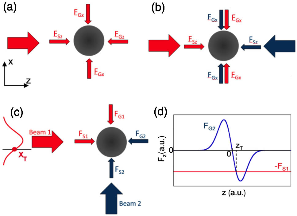
Figure 1.(a) Single-beam tweezer trap (, gradient force; , scattering force), (b) dual-beam trap (Beam 1 is shown in red and Beam 2 is shown in blue to aid in identifying from which beam these forces originated), (c) OBT, and (d) -dependent forces at fixed coordinate highlighted in (c); trapping occurs at , where the gradient force from Beam 2 is restoring.
In order to obtain more quantitative insight into the details of this process, we assume Gaussian beams with equal power and beam widths and consider trapping in the ray optics (large particle) regime. Specifically, we assume identical, collimated Gaussian beams of the form with beam parameter , where is the Gaussian beam waist. This results in scattering and gradient forces are given by where and are constant coefficients, is the particle cross section, is the vacuum speed of light, and and are the usual prefactors for trapping in the ray optics limit [24]. Equivalent equations apply to Beam 2 with an exchange of the coordinates. The necessary force balance condition for particle trapping is thus provided by along the direction and along the direction. By combining Eqs. (4) and (5), we can obtain the single equilibrium position of the OBT as independent of the power in the beams. Figure 1(d) illustrates the equilibrium condition [Eq. (4)]. Due to the beam symmetry, a change in beam power will rescale both lines in Fig. 1(d) in such a way that the intersection of both lines and thus the trapping location determined by Eq. (6) remains the same. The scattering force from Beam 1 is independent of for fixed and assuming a collimated beam. It equals the gradient force created by Beam 2 in two locations, but only the one closer to results in a restoring force required for trapping. Thus, the trapping point location has to be closer to than the location of maximum gradient force . This leads to the stability condition
Equation (7) represents an important new feature of the OBT: trapping can occur for unfocused (collimated) beams, but their beam waist must be small enough to create sufficiently strong gradient forces to compensate the scattering force from the other beam. In addition, we need to take into account that the magnitude of the scattering force depends on the coordinate transverse to the beam direction, e.g., for Beam 1 propagating along , we have . Therefore, the scattering force at the trapping point will be diminished from its on-axis maximum. This fact is represented in Fig. 2(a), which shows the dependence of the scattering force along from Beam 1 and the gradient force along from Beam 2. The figure illustrates that at the equilibrium point, the scattering force from one has to be diminished enough to be compensated by the gradient force from the other beam.
![Analytically calculated forces on microbead in identical collimated beams. (a) Gradient force along z from Beam 2 and scattering force along x from Beam 1 versus transverse coordinate; curves need to intersect between the origin and location of maximum gradient force to form a stable trap [locations of maximum gradient and maximum scattering force used for (b) are shown with green arrows]. (b) Particle size dependence of forces at relevant points (symbols) and fits with second-order polynomial (lines).](/Images/icon/loading.gif)
Figure 2.Analytically calculated forces on microbead in identical collimated beams. (a) Gradient force along from Beam 2 and scattering force along from Beam 1 versus transverse coordinate; curves need to intersect between the origin and location of maximum gradient force to form a stable trap [locations of maximum gradient and maximum scattering force used for (b) are shown with green arrows]. (b) Particle size dependence of forces at relevant points (symbols) and fits with second-order polynomial (lines).
3. APPLICATION
The force curves of Fig. 2(a) were calculated for the specific example of a collimated Gaussian beam (beam waist ; , ) and a microbead particle (index 1.4; diameter ). The gradient force from Beam 2 is plotted along , and the scattering force from Beam 1 is plotted along . We will use this example as the starting point for illustrating the trapping properties of the OBT. In order to calculate realistic forces, we used a formalism for analytical calculation of trapping forces in loosely focused and collimated beams [25]. An infinite number of reflections of a collimated photon stream at the interfaces of a lossless dielectric sphere were considered, and the resulting equations (Eqs. (17) and (18) in [25]) were integrated numerically over all incident angles using MATLAB. The dependence of the gradient and scattering forces at the two relevant locations marked with green arrows in Fig. 2(a) (maximum gradient and maximum scattering forces) are displayed as a function of particle diameter in Fig. 2(b). In the limit of small particles (), the calculated forces (symbols) show good agreement () with parabolic fits (lines) based on the simple relations of Eqs. (2) and (3). In the figure, the stability condition [Eq. (7)] corresponds to the requirement that the curve for the scattering force at the maximum gradient force location be below that for the maximum gradient force, or equivalently . For our specific parameters, this condition is fulfilled for . Once the particle size is comparable to or larger than the beam waist, the scattering force curves deviate from the simple square law of Eq. (2) as expected, since the incident power no longer depends on the particle size once the entire beam hits the particle, and therefore the incident power is constant. As Fig. 2(b) shows, the forces can still be calculated numerically and fulfill the conditions for stable trapping, despite the deteriorating agreement between the parabolic fits and the calculated forces in that range. At the lower end of the displayed particle size where , the Mie scattering regime is approached, but the geometric optics approximation can still be expected to produce acceptable results, especially for collimated beams [26].
Next, we carried out complete dynamic simulations of the particle trajectory under realistic conditions. Again using the beam parameters described above and water as a host medium, the trajectory was calculated by numerically solving the equation of motion shown below in the presence of optical (gradient and scattering) and viscous Stokes drag forces at room temperature (where is the dynamic viscosity; Brownian motion was neglected, since fluctuations in the article location are much smaller than the particle diameter for the parameters considered):
Figure 3(a) shows the trajectory with all dimensions shown to scale. The particle is initially propelled along the center of Beam 1 [as shown in red; see also Fig. 1(c)] under the influence of gradient and scattering forces. Once it enters the channel intersection, it falls into the OBT that is set up by Beams 1 and 2 and comes to a stop at the trapping point . Figure 3(b) provides a different illustration of this process by displaying the sum of the magnitudes of all forces in the and directions around the trapping point. In this representation, a zero value indicates an equilibrium point (no net force on the particle). It can be seen that the optical forces are confined to the beams, and that there is a single point with zero total force at the trapping point close to the center of the intersection. The double peak structures that are visible along both and outside the beam intersection region represent the locations of the maximum gradient force for each beam.
Figure 3.(a) Calculated particle trajectory exhibiting trapping at beam intersection (all dimensions to scale), (b) total force at the beam intersection, trapping point (black), from Beam 1 (red), and Beam 2 (blue) shown with dotted lines, and (c) time dependence of particle velocities along and showing acceleration due to Beam 2, followed by trapping.
Finally, Fig. 3(c) represents the particle velocities along both the and directions as a function of time. After an initial period of constant velocity under the action of the scattering force from Beam 1, the particle briefly speeds up as it enters the intersection region and experiences an acceleration by the gradient force from Beam 2, which points along the positive direction for . After it passes , the particle starts slowing down as the gradient force changes sign, and falls into the trapping location. At the same time, the velocity along is zero until the particle enters Beam 2; at that point there is an acceleration due to , followed by a deceleration due to .
The optical potential along the direction (at ) is shown in Fig. 4(a). It was calculated by integrating the sum of the two forces and [see Fig. 1(d)] along for the specific parameters of our example. The resulting potential has an overall slope caused by the constant scattering force of Beam 1 along with a potential well created by the presence of the gradient force from Beam 2, as discussed in Fig. 1(d) above. As seen in the figure, the confining depth of this potential is , which is sufficient to result in stable trapping in agreement with the dynamic simulations. Finally, we carried out an extended stability analysis by investigating the trapping condition [Eq. (7)] over a wider range of parameters for particle diameters and beam waists. Figure 4(b) shows the resulting stability profile, in which regions of stability and instability are separated by a line. The linear relation implies that trapping is possible at a beam waist of up to 2.4 times the particle diameter for the given set of parameters. For diameters approaching , the stability analysis is only approximate as the Mie regime is reached. For beams with a larger waist, the maximum gradient force is not large enough to compensate for the scattering force exerted by the other beam, and the particle will be deflected but not trapped.
Figure 4.(a) Calculated potential profile along the direction of Beam 1 () and (b) trap stability plot. Symbols delineate the validity limit of the relation in Eq. (7) for a given particle size, and the line shows the linear fit.
The OBT can be implemented in several ways. In free space, a weakly focused Gaussian beam can be used to create the beam waist described above. At , such a beam would have a divergence angle of 9.7° and a focal depth of 8.84 μm. As a result, the beam waist at the trapping location (0.1 μm, 0.1 μm) has increased by only 0.026% from its minimum value, and the beams can be assumed to be collimated over the region of interest. The OBT is even more attractive for integrated photonic structures in which conventional traps based on divergent beams cannot be implemented [15,17]. A fundamental guided mode propagating along a planar waveguide corresponds in excellent approximation to a collimated Gaussian beam [27]. Mode diameters on the order of 0.5–3 μm can easily be achieved in liquid-core waveguides that are large enough to contain microbeads. The parameters from the earlier application are one possible option for a liquid core antiresonant reflecting optical waveguide. Such waveguides can be arranged to create intersecting channels that are precisely aligned and have negligible optical loss over the length scales of interest [28,29].
4. CONCLUSION
In summary, we have introduced a new (to our knowledge) way to trap microparticles using an all-optical particle trap created by orthogonally intersecting, collimated Gaussian beams. This trap creates a combination of gradient and scattering forces that fundamentally differs from the canonical SBTs and DBTs. The properties of the trap were evaluated analytically and numerically, and it was shown that stable trapping of microparticles in the ray optics regime is possible. Extension of the analysis to asymmetric trapping beams is possible but is beyond the scope of this article. The OBT has a number of unique properties [14]. Since it can operate with collimated beams, the trap is ideal for implementation in integrated photonic devices, in particular liquid-core waveguides. The ability to use collimated beams avoids additional problems with nonuniform fluid flow in microchannels of changing dimensions. In addition, the trap is self-loading in the sense that a particle is pushed rapidly toward the trapping point by one beam before being captured by the second. The ability to trap particles with refractive indices on the order of 1.4 in a liquid environment makes this approach very attractive for use with biological particles such as small cells and avoids heating problems associated with highly focused beams in SBTs. Finally, the trap also exhibits unique parameter dependence for stable trapping under a given set of conditions. This may be used to select specific particles from a mixture. Overall, the OBT adds a new approach to the rapidly growing number of techniques for optical particle manipulation in integrated photonic and optofluidic environments.
References
[1] A. Ashkin. Acceleration and trapping of particles by radiation pressure. Phys. Rev. Lett., 24, 156-159(1970).
[2] A. Ashkin, J. M. Dziedzic, J. E. Bjorkholm, S. Chu. Observation of a single-beam gradient force optical trap for dielectric particles. Opt. Lett., 11, 288-290(1986).
[3] S. Chu, J. Bjorkholm, A. Ashkin, A. Cable. Experimental observation of optically trapped atoms. Phys. Rev. Lett., 57, 314-317(1986).
[4] A. Ashkin, J. M. Dziedzic, T. Yamane. Optical trapping and manipulation of single cells using infrared laser beams. Nature, 330, 769-771(1987).
[5] A. Ashkin, J. Dziedzic. Optical trapping and manipulation of viruses and bacteria. Science, 235, 1517-1520(1987).
[6] K. C. Neuman, S. M. Block. Optical trapping. Rev. Sci. Instrum., 75, 2787-2809(2004).
[7] K. Dholakia, T. Čižmár. Shaping the future of manipulation. Nat. Photonics, 5, 335-342(2011).
[8] T. Čižmár, M. Mazilu, K. Dholakia. In situ wavefront correction and its application to micromanipulation. Nat. Photonics, 4, 388-394(2010).
[9] V. Karásek, T. Čižmár, O. Brzobohatý, P. Zemánek. Long-range one-dimensional longitudinal optical binding. Phys. Rev. Lett., 101, 143601(2008).
[10] S. Kawata, T. Sugiura. Movement of micrometer-sized particles in the evanescent field of a laser beam. Opt. Lett., 17, 772-774(1992).
[11] A. E. Cohen. Suppressing Brownian motion of individual biomolecules in solution. Proc. Natl. Acad. Sci. USA, 103, 4362-4365(2006).
[12] F. Amblard, B. Yurke, A. Pargellis, S. Leibler. A magnetic manipulator for studying local rheology and micromechanical properties of biological systems. Rev. Sci. Instrum., 67, 818-827(1996).
[13] M. J. Lang, S. M. Block. Laser-based optical tweezers. Am. J. Phys., 71, 201-215(2003).
[14] A. Ashkin. Optical Trapping and Manipulation of Neutral Particles Using Lasers(2006).
[15] S. Kühn, P. Measor, E. J. Lunt, B. S. Phillips, D. W. Deamer, A. R. Hawkins, H. Schmidt. Loss-based optical trap for on-chip particle analysis. Lab Chip, 9, 2212-2216(2009).
[16] S. Cran-McGreehin, T. F. Krauss, K. Dholakia. Integrated monolithic optical manipulation. Lab Chip, 6, 1122-1124(2006).
[17] S. Kühn, B. S. Phillips, E. J. Lunt, A. R. Hawkins, H. Schmidt. Ultralow power trapping and fluorescence detection of single particles on an optofluidic chip. Lab Chip, 10, 189-194(2010).
[18] A. H. J. Yang, S. D. Moore, B. S. Schmidt, M. Klug, M. Lipson, D. Erickson. Optical manipulation of nanoparticles and biomolecules in sub-wavelength slot waveguides. Nature, 457, 71-75(2009).
[19] S. Lin, E. Schonbrun, K. Crozier. Optical manipulation with planar silicon microring resonators. Nano Lett., 10, 2408-2411(2010).
[20] S. Mandal, X. Serey, D. Erickson. Nanomanipulation using silicon photonic crystal resonators. Nano Lett., 10, 99-104(2010).
[21] C. Adams, H. Lee, N. Davidson, M. Kasevich, S. Chu. Evaporative cooling in a crossed dipole trap. Phys. Rev. Lett., 74, 3577-3580(1995).
[22] S. Chaudhuri, S. Roy, C. S. Unnikrishnan. Evaporative cooling of atoms to quantum degeneracy in an optical dipole trap. J. Phys. Conf. Ser., 80, 012036(2007).
[23] M. Barrett, J. Sauer, M. Chapman. All-optical formation of an atomic Bose–Einstein condensate. Phys. Rev. Lett., 87, 010404(2001).
[24] A. Ashkin. Forces of a single-beam gradient laser trap on a dielectric sphere in the ray optics regime. Biophys. J., 61, 569-582(1992).
[25] S. B. Kim, S. S. Kim. Radiation forces on spheres in loosely focused Gaussian beam: ray-optics regime. J. Opt. Soc. Am. B, 23, 897-903(2006).
[26] P. A. M. Neto, H. M. Nussenzveig. Theory of optical tweezers. Europhys. Lett., 50, 702-708(2000).
[27] D. Yin, J. P. Barber, A. R. Hawkins, H. Schmidt. Waveguide loss optimization in hollow-core ARROW waveguides. Opt. Express, 13, 9331-9336(2005).
[28] P. Measor, S. Kühn, E. J. Lunt, B. S. Phillips, A. R. Hawkins, H. Schmidt. Hollow-core waveguide characterization by optically induced particle transport. Opt. Lett., 33, 672-674(2008).
[29] D. Yin, E. J. Lunt, A. Barman, A. R. Hawkins, H. Schmidt. Microphotonic control of single molecule fluorescence correlation spectroscopy using planar optofluidics. Opt. Express, 15, 7290-7295(2007).


