• Chinese Journal of Lasers
  • Vol. 49, Issue 8, 0802009 (2022)
Zhen Dou1, Yuyue Wang1, Anfeng Zhang2、*, Mengjie Wu2, and Puqiang Wang1
Author Affiliations
  • 1State Key Laboratory for Mechanical Behavior of Materials, Xi'an Jiaotong University, Xi'an 710049, Shaanxi, China
  • 2State Key Laboratory for Manufacturing Systems Engineering, Xi'an Jiaotong University, Xi'an 710054, Shaanxi, China
  • show less
    DOI: 10.3788/CJL202149.0802009 Cite this Article Set citation alerts
    Zhen Dou, Yuyue Wang, Anfeng Zhang, Mengjie Wu, Puqiang Wang. Effect of Different Heat Treatments on Microstructure, Properties, and Anisotropy of SLM TC4[J]. Chinese Journal of Lasers, 2022, 49(8): 0802009 Copy Citation Text show less
    Schematic diagram of SLM TC4 sample forming method and size. (a) Schematic of horizontal specimen;(b) schematic of vertical specimen; (c) physical drawing of horizontal forming; (d) physical drawing of vertical forming
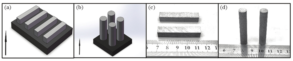
    Fig. 1. Schematic diagram of SLM TC4 sample forming method and size. (a) Schematic of horizontal specimen;(b) schematic of vertical specimen; (c) physical drawing of horizontal forming; (d) physical drawing of vertical forming
    Macro morphology of SLM TC4. (a) SLM-V; (b) SLM-H
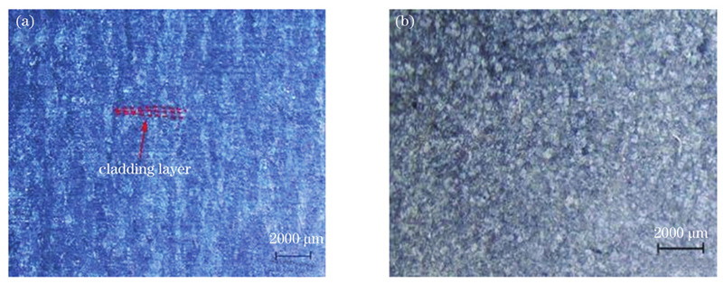
    Fig. 2. Macro morphology of SLM TC4. (a) SLM-V; (b) SLM-H
    Images of low-magnification microstructure of SLM TC4 deposited state and different heat treatment processes. (a) As-deposited; (b) HM1; (c) HM2; (d) HM3
    Fig. 3. Images of low-magnification microstructure of SLM TC4 deposited state and different heat treatment processes. (a) As-deposited; (b) HM1; (c) HM2; (d) HM3
    SEM images of low-magnification microstructure of SLM TC4 deposited state and different heat treatment processes. (a) As-deposited; (b) HM1; (c) HM2; (d) HM3
    Fig. 4. SEM images of low-magnification microstructure of SLM TC4 deposited state and different heat treatment processes. (a) As-deposited; (b) HM1; (c) HM2; (d) HM3
    Anisotropic histogram of microstructure in deposited state and different heat treatment processes
    Fig. 5. Anisotropic histogram of microstructure in deposited state and different heat treatment processes
    Tensile stress state of grain boundaries in different directions and crack propagation path diagram. (a) SLM-H;(b) SLM-V; (c) schematic diagram of crack propagation pathin deposited state and after heat treatment
    Fig. 6. Tensile stress state of grain boundaries in different directions and crack propagation path diagram. (a) SLM-H;(b) SLM-V; (c) schematic diagram of crack propagation pathin deposited state and after heat treatment
    Tensile fracture morphology of SLM TC4 in deposited state. (a) SLM-H(×80); (b) SLM-H(×2000); (c) SLM-H(×5000); (d) SLM-V (×80); (e) SLM-V(×2000); (f) SLM-V(×5000)
    Fig. 7. Tensile fracture morphology of SLM TC4 in deposited state. (a) SLM-H(×80); (b) SLM-H(×2000); (c) SLM-H(×5000); (d) SLM-V (×80); (e) SLM-V(×2000); (f) SLM-V(×5000)
    Topography of the tensile fracture of different heat treatment processes. (a) HM1-H(×80); (b) HM1-H(×2000); (c) HM1-V(×80); (d) HM1-V(×2000); (e) HM2-H(×80); (f) HM2-H(×2000); (g) HM2-V(×80); (h) HM2-V(×2000); (i) HM3-H(×80); (j) HM3-H(×2000); (k) HM3-V(×80); (l) HM3-V(×2000)
    Fig. 8. Topography of the tensile fracture of different heat treatment processes. (a) HM1-H(×80); (b) HM1-H(×2000); (c) HM1-V(×80); (d) HM1-V(×2000); (e) HM2-H(×80); (f) HM2-H(×2000); (g) HM2-V(×80); (h) HM2-V(×2000); (i) HM3-H(×80); (j) HM3-H(×2000); (k) HM3-V(×80); (l) HM3-V(×2000)
    ElementAlVFeCNHOTi
    Mass fraction /%6.013.920.1640.0050.0020.0010.072Bal.
    Table 1. Chemical composition of TC4 powder
    No.Heat treatment processes
    SLMAs-built
    HM1TC4 samples are first air cooled after solution treatment at 950 ℃ for 1 h, and then air is cooled after aging at 550 ℃ for 4 h.
    HM2TC4 samples are heated to 920 ℃ for 5 min, then cooled to 700 ℃ for 10 min in the furnace, which is repeated five times and then samples are air cooled.
    HM3TC4 samples are kept at 920 ℃ for 10 min, cooled slowly to 800 ℃ and kept for 30 min in the furnace. When the temperature is 550 ℃,samples are immediately heated to 920 ℃. The whole process is repeated for 4 times and then samples are cooled in the furnace. At last the solution heat treating is performed at 920 ℃ for 1 h and aging treatment is performed at 550 ℃ for 4 h.
    Table 2. Heat treatment processes of SLM TC4 alloy
    TreatmentTensile directionUltimate tensile strength σb/MPaYield strength σs/MPaElongation /%Rate of reduction in area /%
    SLMH1226.0±19.541048.2±19.1513.1±1.1642.6±1.85
    V1220.0±8.081060.2±8.2111.5±1.8240.2±2.32
    HM1H952.4±3.61862.4±3.2617.5±1.7949.2±1.17
    V963.4±3.38868.4±7.0017.7±1.2148.8±1.94
    HM2H883.8±4.92792.2±6.3118.8±1.5445.4±1.02
    V893.4±7.94807.6±8.2117.4±1.5648.0±1.41
    HM3H936.6±4.84848.6±3.2619.1±1.7747.0±2.97
    V955.8±4.71865.6±2.9417.6±2.2748.4±1.02
    GB/T 25137-201089582810.025.0
    Table 3. Mechanical properties of SLM TC4 alloy tensile specimens under different treatment conditions
    Zhen Dou, Yuyue Wang, Anfeng Zhang, Mengjie Wu, Puqiang Wang. Effect of Different Heat Treatments on Microstructure, Properties, and Anisotropy of SLM TC4[J]. Chinese Journal of Lasers, 2022, 49(8): 0802009
    Download Citation