Abstract
The electronic paper (E-paper) displays features such as flexibility, sunlight visibility, and low power consumption, which makes it ideal for Internet of Things (IoT) applications where the goal is to eliminate bulky power modules. Here, we report a unique self-powered E-paper (SPEP), where information inputs and energy supplies are all converted from mechanical motion by a triboelectric nanogenerator (TENG). The operation of an electrophoretic E-paper is first investigated, identifying the current density as a determinative parameter for driving pigment particle motion and color change. Electrical and optical responses of the E-paper driven by a sliding-mode TENG are then found to be consistent with that under a current source mode. All-in-one monochromic and chromatic SPEPs integrated with a flexible transparent TENG are finally demonstrated, and a pixelated SPEP is discussed for future research. The sliding-driven mechanism of SPEP allows for a potential handwriting function, is free of an extra power supply, and promises undoubtedly a wide range of future applications.1. INTRODUCTION
Currently, low power consumption is widely pursued by portable/wearable electronics. In the meantime, smart sensor networks of the emerging Internet of Things (IoT) have to be self-powered by energy in situ harvested from the working environment to avoid impossible maintenance of numerous smart devices [1,2]. Thus, commercial display devices such as liquid crystal display (LCD) or organic light-emitting diode (OLED) fail to satisfy the requirement of low power consumption. This growing demand brings electronic paper (E-paper) uniquely new opportunities, if a low power E-paper can be integrated with an energy-generating device for self-powered displays.
E-paper is a unique type of display, whose reflective mode operation exploits environmental light sources to show images. Further, the bistability feature causes it to require external driving only while updating the image content [3]. These two features create the E-paper display of low power consumption and high outdoor contrast and, thus, great potential in various applications such as education, office, advertisement, and smart retailing. In electrophoretic E-papers—the most successfully commercialized E-paper technology—there are generally different color particles, and these particles are usually surface-modified and charged by charge control agents (CCAs) for excellent stability in the nonpolar solvent [4–7]. The color of a pixel is updated by changing the distribution of charged pigment particles of different colors between two electrodes with an external electric field. The driving current is contributed by the fluxes of both charged pigment particles and reversed micellar aggregations of redundant CCAs. With the specific driving waveforms [8–10], different distributions of pigment particles are formed to provide various colors according to Grassmann’s laws, which indicate the possibility of a full-color E-paper [11].
The triboelectric nanogenerator (TENG) is an emerging technology that converts mechanical energy into electricity through the coupling of the triboelectric effect and electrostatic induction [12–14]. The TENG has been demonstrated to be highly efficient in generating electricity from low-frequency mechanical motions [15,16] such as touching, sliding, stretching, and vibrating [17–22]. This highly efficient energy transformation makes TENG an excellent choice for self-powered displays. Besides, a TENG can be transparent, flexible, or stretchable because of its versatility in structure and material design [23–33]. In recent years, great development has been achieved for TENG, which provides broad applications for TENG in various fields, including the display field [34–36]. In previous reports, electroluminescence technology was combined with TENG as an integrated self-powered display, which revealed its great potential [37–39]. Nevertheless, use of self-powered, bistable displays like the E-paper is more advantageous than use of electroluminescence displays.
Sign up for Photonics Research TOC. Get the latest issue of Photonics Research delivered right to you!Sign up now
In this paper, an all-in-one integrated self-powered E-paper (SPEP) display was demonstrated. Since minimal research has been done on the coupling of the E-paper and TENG, we focused on the optimization of SPEP driven by TENG. First, the particle behavior was studied for a better understanding of the internal process inside the E-paper. Through that, the electrical model of the E-paper driven by TENG was established to improve the performance of SPEP following specific rules. Besides, a transparent TENG was integrated into SPEP to minimize its influence on the display. Further, a pixelated SPEP is discussed for future research. Under the background of IoT, mechanical-triggering color/image change mechanisms can possibly endow SPEP with unexplored applications.
2. RESULTS AND DISCUSSION
A. Concept of SPEP
An SPEP display was proposed in this study by driving the electrophoretic E-papers solely with the current generated by a sliding-mode TENG, as shown in Fig. 1(a). The SPEP features two characteristics that differentiate it from previous displays: (i) no external electrical power source is connected to drive the E-paper; and (ii) both the color change of a pixel and the updating of a display image are triggered and driven solely by mechanical touching or sliding motions. Other than supplying power, the sliding motions can also provide information input for visual outputs of the SPEP, differentiating it from current displays and suggesting potentially vast opportunities for future applications. In each pixel, a TENG can be directly mounted on the E-paper, with a rectifier to convert alternating current (AC) of the TENG to direct current (DC) for driving the color change and a bidirectional switch to change the current directions applied on the E-paper. Due to the flexible form factors of both the TENG and the E-paper, the SPEP is also flexible. If the TENG is designed with transparent electrodes and dielectric tribomaterials, either side of the SPEP can be used for display; otherwise, an opaque TENG allows one-side display, and the mechanical input and display cannot be on the same side. The TENG can be designed into the contact-separation mode or sliding mode [40].
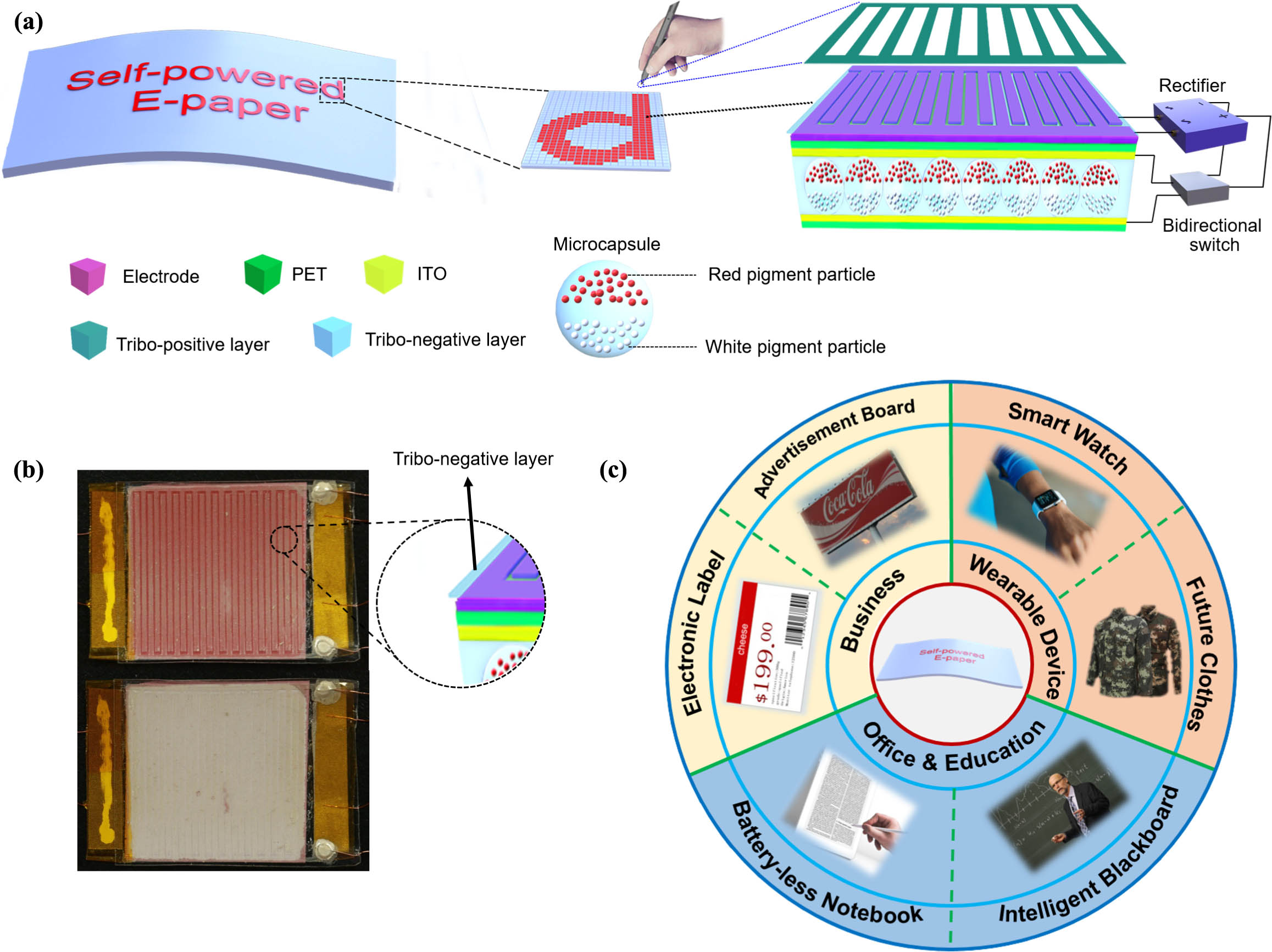
Figure 1.Concept of self-powered E-paper (SPEP). (a) Schematical illustration of an SPEP with handwriting input and its structure in a pixel. (b) Prototype of the chromatic type SPEP before and after one-time color changing. (c) Possible applications of the SPEP in various fields.
In this study, a sliding-mode TENG with interdigitated electrodes was adopted for demonstration [Fig. 1(a)]. The slider made of tribopositive materials has the same structure as one of the finger electrodes. A microcapsule-type electrophoretic E-paper was adopted, which was chromatic using ferric oxide (red) and titanium dioxide (white) as pigment particles. Moreover, other types of E-paper were also prepared for experiments, which used carbon black (monochromic) and green rust (green) as pigment particles, respectively. Figure 1(b) shows an integrated SPEP with a transparent TENG on the top. By rubbing it with a slider, the color was changed (from red to white).
The SPEP is flexible and external power free, and could be actuated by mechanical inputs, suggesting various application scenarios in many fields [see Fig. 1(c)]. For example, the SPEP with handwriting input can be used in the office to replace actual papers, which also reduces cost and is eco-friendly. It can be used as smartboards or notebooks for better education experiences since it requires no battery recharging or external power source and causes less visual fatigue. It may also be used as self-powered electronic billboards and E-labels in remote areas where electricity sources are difficult to find. It also has enormous potential in wearable devices as self-powered flexible displays or color-changing clothes for camouflage or fashion.
B. Particle Behavior Inside the E-Paper
In order to optimize the driving process, the operational mechanisms of E-papers should be understood in detail. The typical behavior of particles inside an E-paper was investigated by analyzing their optical and electrical responses when driving the E-paper using a simple square waveform [Fig. 2(a)], since the complex driving waveforms for commercial E-paper can be assembled by square waveforms. The optical response of the E-paper can be characterized by the intensity of reflective light, which describes the particle movements and distribution inside the E-paper. The in situ observation of an individual microcapsule under an optical microscope is shown in Fig. 2(b), which was supported by Visualization 1.

Figure 2.Operational characteristics of a monochromic E-paper under the voltage pulse mode. (a) Profiles of driving current, equivalent impedance, and intensity of reflective light during each driving process by a constant voltage. (b) Schematic diagrams of the identified five stages and in situ optical microscopy photos of an individual microcapsule. Profiles of (c) current and (d) equivalent impedance of the E-paper driven by different voltages.
Five stages were identified in each driving process. Before applying an external voltage, white and black particles were distributed at the two opposite sides of the microcapsule, respectively. There was no current, and the E-paper remained stable without changing in grayscale (T0 stage). Upon applying an external electrical field, the charged particles in the dispersion, including reversed micelles and pigment particles, started to be actuated and accelerated, which led to the quick change of the grayscale (T1 stage). At the same time, almost all the charged particles inside the E-paper participated in electrophoresis, so that the current reached the maximum value quickly.
In the T2 stage, most of the particles arrived at the electrode boundaries, and the number of moving particles decreased gradually. Therefore, the variation of reflective light intensity slowed down. Since most of the pigment particles stopped moving, the driving current was therefore gradually reduced, while the equivalent impedance gradually increased. The T3 stage was the over-driving stage, which means almost all pigment particles reached the counter electrodes, as the grayscale was kept constant. At the same time, since most of the pigment particles stopped, the current generated came only from the motion of reversed micelles, which were continuously generated nearby the electrode. This current was called a steady-state current [41]. Besides, positive and negative pigment particles (reversed micelles as well) were concentrated at the two electrodes, respectively, forming a built-in electrical field with a direction opposite to the driving voltage. The built-in electrical field had been accumulating during the T3 stage, which is shown by the color depth in Fig. 2(b).
After removing the external field (T4 stage), pigment particles concentrating at the surfaces of two electrodes would shift away from electrodes for a short distance due to the built-in electrical field, which led to a small reverse current. As the particles shifted, the built-in electrical field gradually weakened, and the reverse current also gradually decreased. This phenomenon is usually called grayscale degeneration, which has been reported in previous literature [42]. At this stage, the grayscale of the E-paper regressed slightly for a while but finally became stable, which is due to a balance between the forces (rheological friction, buoyancy, gravity, and electrostatic forces) applied on the particles. T1–T5 stages can be confirmed by in situ observation of an individual microcapsule, and they are schematically described accordingly in Fig. 2(b).
While increasing the driving voltage, the current increased as well because more charged particles were driven, including pigment particles and the reversed micelles [Fig. 2(c)]. Furthermore, the time of T2 stage was shortened with higher driving voltage, since pigment particles moved toward the opposite electrode faster. T1–T3 stages were roughly divided with different colors in Figs. 2(c) and 2(d). It should be noticed that the equivalent impedance overlapped at all starting points of curves in Fig. 2(d) and tended to be the same after driving by voltage higher than 5 V. This revealed that for the same piece of E-paper, the equivalent impedance was determined mainly by the grayscale (i.e., the distribution of pigment particles).
C. Significance of Current Density for Driving E-Paper
To pursue better performance of the SPEP, it is essential to analyze the circuit model and come up with a more suitable design rule for integrated SPEP devices. Generally, the TENG is featured as a current source with high internal impedance [43]. Therefore, the driving characteristics of the E-paper through constant current and constant voltage sources were compared. E-papers with different sizes were respectively driven by a 5 μA constant current source [Fig. 3(a)] and a 5 V constant voltage source [Fig. 3(a)]. After being driven by the constant voltage sources (4 s), E-papers with different sizes kept the same grayscale [see the inset in Fig. 3(b)]. However, when E-papers with different sizes were driven by the constant current source, the variation in the grayscale was reduced with increase in the size of the E-paper [see the inset in Fig. 3(a)].
Figure 3.Comparison of the E-paper driven by constant current and voltage sources. V-t and I-t plots of various sizes of E-papers under (a) current source mode and (b) voltage source mode, respectively. The inset photos show their correspondent grayscales. Equivalent electrical circuits and schematic diagrams of the E-paper driven by (c) a constant current source and (d) a constant voltage source are illustrated, respectively.
An E-paper can simply be termed as a resistor and a capacitor in parallel connection [44]. We assume that the resistance and capacitance of an E-paper unit () are and , respectively. The E-paper with area is equivalent to several (the number is ) E-paper units in parallel connection [see Fig. 3(c)], and these units are in the same states. With constant current [see Fig. 3(c)], the current passing through each parallel-connected unit is (i.e., current density). The driving force () for a single pigment particle can be estimated as Eq. (1), where is the distance between two electrodes of E-paper, is the charge of the particle, and is the impedance of an E-paper unit (). Therefore, the driving force will decrease with the increasing number of E-paper units (i.e., increasing the area). If the driving force is too small, a part of the sluggish particles (heavier and/or less charge) will not move, and the grayscale change of the E-paper will decrease even if enough time is given, which coincides with the observation made in Fig. 3(a). In contrast, at the constant voltage mode, ideally, the voltage and current density of the E-paper are always and , respectively [Fig. 3(d)]. The grayscale change will be independent of the E-paper area since the driving force is about the same. It should be noted that once the grayscale of E-paper and the distribution of the pigment particles change, there must be a current caused by the moving of pigment particles. Furthermore, it could also be concluded that driving current density, despite the driving mode, is the parameter directly characterizing the behavior of pigment particles inside the E-paper, as it determines the amount of actuated pigment particles and has a significant influence on the grayscale of E-paper:
D. Characteristic Responses of the E-Paper Driven by a Sliding-Mode TENG
Since the current density applied on an E-paper must be high enough to maximize the grayscale change, a sliding-mode TENG is adopted due to its high current output [16,45,46]. The operation mechanism of the TENG is schematically shown in Fig. 4(a). The TENG is composed of a stator and a slider. The stator has two interdigitated electrodes, on the top of which is a dielectric polytetrafluoroethylene film (PTFE), and the nickel (Ni) slider has the same structure as one finger electrode [the photo in Fig. 4(a)]. By horizontally sliding the slider, static negative and positive charges are generated on the surface of the PTFE and Ni slider, respectively, due to their difference in work functions [47]. When the slider moves forward, a current will be generated flowing from the right to left electrode, due to the electrostatic induction effect, to achieve the local charge balance. The external current direction will be reversed by sliding the slider backward. As the sliding motions repeat, an AC is generated, as shown in Fig. 4(b). Each one-way sliding will produce an AC pulse, as depicted in the enlarged graph in Fig. 4(b). The maximum current amplitude () and the frequency () of the AC inside each pulse can be described as Eqs. (2) and (3) [16,46]. In these two equations, is the number of Ni segments in the slider, is the electrostatic charge density on PTFE surface, is the speed of the slider, is the gap between the two interdigitated electrodes, and and are the width and length of each finger electrode segment, respectively:
A maximum short-circuit current peak of was obtained for a TENG sliding at 0.5 m/s speed (, , , and ), as shown in Fig. 4(b). For TENGs with the same total area (), increasing segment number by reducing the segment width can certainly improve the maximum current. As confirmed by Fig. 4(c), is proportional to the sliding speed and inversely proportional to the finger electrode width ( is 0.5 mm and is 37 mm for all samples).
Figure 4.Characteristics of the sliding-mode TENG and typical responses of the E-paper driven by the TENG. (a) Working mechanism of the sliding-mode TENG and its photo. (b) The output short-circuit current of a TENG. (c) The summarized maximum amplitude of a short-circuit current of TENG with different structural parameters and sliding speeds. (d) The peak current of the TENG at different external loading resistance. (e) The rectified short-circuit current of the TENG. (f) Peak output power of a TENG ( and ) at different external loading resistance. (g)‒(i) Current (inset is the peak current), voltage (inset is the valley value of voltage), and grayscale change (insets are photos of E-papers) of an E-paper driven by the TENG, respectively. Other than (c), all are measured with TENG parameters of and .
Figure 5.Influential parameters for driving E-papers with the TENG. (a) Grayscale changes of the E-paper driven by TENGs with different electrode widths (, ). (b) Grayscale changes of the E-paper driven by TENGs at different sliding speeds (, ). (c) Grayscale changes of the E-paper with different sizes (, ). (d) Photos of grayscale changing of monochromic and chromatic E-papers () along with sliding motion times of the TENG.
When the impedance of the external load is low, the current passing the load is kept almost invariably close to that of short-circuit conditions, as the internal impedance of TENG is high. This phenomenon could be confirmed in Fig. 4(d), where the measured current remained approximately 10 μA until the resistance of the external load reached . Maximum power was obtained at a matched resistance of [Fig. 4(f)]. A relatively stronger built-in electrical field was supposed to explain the difference of impendence between different driving methods ( for DC driving and for TENG driving). As we mentioned in Section 2.B, a built-in electrical field was formed by the charged particles during the driving process, which influenced the equivalent impedance of the E-paper. At the end of the T3 stage, the weakened driving electric field was not enough to drive some remaining pigment particles. However, when the E-paper was driven by the TENG, there must be some pigment particles driven to the driving electrodes to contribute to the driving current for every sliding of the TENG until almost all pigment particles are concentrated at the driving electrodes; this forms a stronger built-in electrical field and leads to a higher equivalent impedance.
After rectifying the AC of TENG into a DC [Fig. 4(e)], it was used to drive a monochromic E-paper (). The current [Fig. 4(g)], voltage [Fig. 4(h)], and whiteness [Fig. 4(i)] of the E-paper were recorded during the driving process. The current amplitude at the first sliding (7.2 μA) was slightly lower than that of a short-circuit condition [8.7 μA in Fig. 4(e)], but it decreased dramatically in the following five slidings and stabilized at a low level less than 1 μA after [see also the inset in Fig. 4(g)]. This phenomenon suggests that the impedance of the E-paper would increase during the driving process because of the arrival of pigment particles at the counter electrodes and the decrease in the quantity of moving charged particles. In the meantime, the voltage dramatically increased in the first five slidings and reached stabilization, similar to the observed trend at the current source mode in Fig. 3(a). The arrival of pigment particles at the counter electrode is further supported by a rapid decrease in whiteness after the first five slidings (from 0.51 to 0.08) and the color change of the E-paper [inset photos in Fig. 4(i)]. These observations, following the particle behaviors previously mentioned, demonstrate that the E-paper works at the current source mode when driven by a sliding TENG.
E. Influential Parameters of the TENG for Driving E-Paper
The decisive parameter determining the grayscale change is the current density passing through an E-paper, as discussed in Section 2.C. Therefore, the sliding speed () and finger electrode width () of the TENG, and the area of the E-paper were varied to investigate their effects on grayscale change, because they were all related to the current density. By decreasing only the electrode width, the whiteness change of a monochromic E-paper was enlarged and required sliding times are reduced, as shown in Fig. 5(a) (). Similar trends could also be achieved by increasing only the sliding speed, as depicted by Fig. 5(b) (, E-paper area ). These trends come from the higher output current of the TENG at the smaller electrode width and the higher sliding speed. Reducing the area of E-papers has also led to a more obvious whiteness change ratio driven by a TENG of the same condition (, ), as shown by Fig. 5(c).
These results are in accordance with the previously mentioned discussion in Section 2.C: the current density applied on the E-paper should be large enough to achieve high whiteness contrast when driving it by a TENG; otherwise, more sliding times are required while slowing of the pigment particles still cannot be actuated. The data also suggest that the grayscale change of the E-paper can be controlled by the mechanical motion inputs (sliding speed and times) of the TENG. For example, grayscales or colors of three E-papers (monochromic, red, and green) changed gradually after each sliding of the TENG, as shown by the photographs in Fig. 5(d). Visualization 2 shows that three types of colored E-papers can be easily driven by TENG using one-time hand sliding.
F. SPEP Prototypes Integrated with Transparent TENGs
For self-powered display, it is better to integrate the TENG and E-paper into one piece and to place mechanical inputs and visual outputs into one screen. Therefore, an integrated SPEP was fabricated with a transparent sliding-mode TENG on the top, as shown in Fig. 6(a).
Figure 6.Self-powered E-paper (SPEP) integrated with a transparent TENG. (a) Schematic illustration of an all-in-one SPEP with a transparent TENG on the top. (b) The rectified short-circuit current of the TENG with hand sliding (). (c) Transmittance and photos (inset) of the transparent TENG. (d) The grayscale changes and inset photos of the SPEP driven by hand sliding. (e) The grayscale of the E-paper before and after bending.
For further optimization, a transparent fluorinated ethylene propylene (FEP) film and a silver nanowire (AgNW) film were utilized as electrification layers and electrodes, respectively. The tribopositive slider does not have to be transparent. A bidirectional switch was used to switch the current direction for rewritable or repeatable color change. The TENG averaged a transmittance of 89% in the visible light range and remained flexible, as shown by Fig. 6(c) and the inset photos. When sliding the Ni slider by hand, the transparent TENG could output a short-circuit AC with a peak amplitude of about 7 μA (, , , and ). Figure 6(b) shows the rectified short-circuit DC. When sliding the monochromic SPEP by hand, the whiteness decreased from 0.49 to 0.06 after five sliding motions, and dramatic grayscale changes could also be confirmed, as shown in Fig. 6(d) and the inset photos. The color change of chromatic SPEP (red) can be found in Fig. 1(b). Visualization 3 shows the sliding-driven color change of a monochromic SPEP and a chromatic SPEP. It is worth noting that the area of the transparent TENG () in these demos was slightly smaller than that of the underlying E-paper (), which made it possible to fabricate self-powered display panels with demonstrated SPEP pixels. Note that the E-paper is also flexible, as supported by Fig. 6(e) and Visualization 4, and that makes the flexible integrated SPEP possible.
G. Brief Discussion About a Pixelated SPEP in Future Research
In order to achieve various applications in the future, a pixelated SPEP device is required for display. In this section, two kinds of pixelated SPEP structures and their driving are discussed. As a feasible solution, TENG could be integrated with power storage and a management module for the driving of the E-paper. Since the energy harvested by TENG was first stored by the management module, the E-paper could be driven by conventional DC waveforms, which was cited in the introduction.
However, in future research, an easy and straightforward structure is preferred, in which every single pixel of an E-paper is independently driven by a TENG integrated onto the surface of pixel. The theoretical analysis of this structure could be simplified to focus on the single pixel of SPEP with scaling down the size but not changing the structure of SPEP. It should be assumed that the functional area of the E-paper is the same as the TENG in a single pixel and the area of single pixel (). As the driving current density is emphasized in the paper, we suppose that the output current peak of TENG () should be higher than the maximum of driving current () during the driving process of the E-paper. In Section 2.B, the maximum of the driving current occurred when the driving process began, which is because almost all the charged particles were driven and contributed to the driving current. Thus, the maximum driving current for a single pixel of E-paper can be described by Eq. (4), which is correlated to the area of the pixel. In Eq. (4), is the quantity of electric charge, is the density of charged particles, and is the velocity of the charged particles. Further, subscript is for pigment particles, and subscript is for charged reversed micelles. In Eq. (2) in Section 2.D, output current peak of TENG can be described by Eq. (5), which is correlated to the square root of the area of the pixel. From these equations, it can be concluded that decreased more rapidly than as the area of the pixel decreased. Moreover, the single-pixel integrated SPEP was successfully driven with the integrated TENG in Section 2.F. Thus, we suppose that the SPEP with smaller pixel size can also be driven by the integrated TENG as the conclusion for the analysis:
At present, the size of a single pixel of an E-paper could be as small as approximately 150 μm. The size of the TENG in our work is about centimeter-scale, with the finger electrode width in millimeter-scale. However, TENG could be scaled down to about several hundred microns with micromachining technology, e.g., lithography technology. As a rough prediction, the size of a single pixel of the SPEP could be about 100 μm in the future. As an opinion when designing waveforms for E-paper driven by TENG, we suppose that some principle in DC driving for E-papers is also practical for TENG driving, which should be considered. Furthermore, machine learning may be a powerful tool for waveform design in the future.
3. EXPERIMENTAL SECTION
A. Characterization of the Optical and Electrical Performance of E-Paper
In order to investigate the optical and electrical performance of E-paper, an experimental setup was established. An E-paper sample was illuminated by white light from a constant light source (GCI-060411, Daheng Optics Co., Ltd.), while the reflective light was captured by a photo-detector (DH-GDT D020V, Daheng Optics Co., Ltd.) to record the variation of light intensity. The driving current and voltage were measured by digital oscilloscope Picoscope 6 (Pico Technology Inc.). To examine the electrical responses of E-papers under constant current or constant voltage driving modes, a sourcemeter Keithley 2400-C was utilized to collect voltage data when applying a constant current or to collect current data when applying a constant voltage to the E-paper. Different measurement data in Fig. 2(a) were synchronized indirectly through the driving voltage data, which was respectively measured by both the digital oscilloscope Picoscope 6 and the sourcemeter Keithley 2400-C with the same sampling rate. Considering characteristics of E-paper as a reflective display, a spectrophotometer i1 Pro (Xrite Inc.) was utilized to measure the whiteness of E-paper.
B. Fabrication of the Sliding-Mode TENG
The TENG was composed of a stator and a slider, as shown by photos in Fig. 4(a). The commercial conductive cloth was fixed on an acrylic plate and was cut into an interdigitated shape by a computer-controlled laser cutting machine. A polytetrafluoroethylene (PTFE) tape is placed over the interdigitated electrodes. The electrode widths of the three stators were 1, 2, and 4 mm, respectively. The length and gap of the electrodes were continuously kept as 37 mm and 0.5 mm, respectively. The number of fingers in each electrode was 34, 20, and 11, respectively, so that the total area of the stators was about the same. The Ni strip width and length of the slider are the same as those of the stator; the Ni strip gap was 2, 3, and 5 mm, respectively.
C. Fabrication of the Transparent TENG and All-In-One SPEP
A Kapton tape was attached on a commercial transparent polyethylene terephthalate (PET) film, and was cut into a designed interdigitated shape by a laser cutter for using as a mask. The width and gap of the electrode were 1 mm and 0.5 mm, respectively. The intensity of the laser was controlled to cut through only Kapton without damaging the PET film below. A total of 2 mg/mL of Ag NW dispersions in isopropanol was uniformly sprayed onto the mask-attached PET film by a spray gun to form a transparent conductive network. After removing the Kapton mask, two transparent interdigitated electrodes (, , , and ) were obtained. After that, a transparent FEP film was attached on the transparent electrodes. The prepared transparent TENG stator was mounted on an electronic paper with a slightly larger area () by a commercial very high bond tape. The rectifier and bidirectional switch were soldered into the circuit.
D. Measurement of the TENG Output
The sliding speed of the TENG was controlled by a linear motor. The output and rectified short-circuit current of the TENG were measured by the Keithley 6514 electrometer. The voltage and current when the TENG drives the E-paper were also measured by 6514 system electrometers.
4. CONCLUSION
In summary, we propose that SPEP utilizes mechanical motion as information input and energy sources with the aid of a triboelectric nanogenerator. By investigating the pigment particle behaviors, we found that the current density applied on an E-paper, despite the driving modes, is the determinative parameter for the color/grayscale change. A sliding-mode TENG was adopted to drive the E-paper, and the response of the E-paper was found to be consistent with that under a current source mode. By investigating the effects of the TENG’s structure parameters (sliding speed, electrode width), an all-in-one integrated SPEP was finally achieved with an integrated transparent TENG. Besides, a pixelated SPEP was briefly discussed for future research. Our SPEP consumes no additional electrical power source and triggers the color change by mechanical motions, making bistable and reflective self-powered displays or self-powered touchscreens possible. Future efforts are still required mainly for the following two aspects: (i) transparent TENGs outputing high current density and working at arbitrary sliding/touching directions and (ii) large-area fabrication of the SPEP pixels into display panels.
References
[1] Z. L. Wang. On Maxwell’s displacement current for energy and sensors: the origin of nanogenerators. Mater. Today, 20, 74-82(2017).
[2] Z. L. Wang. Entropy theory of distributed energy for internet of things. Nano Energy, 58, 669-672(2019).
[3] J. Heikenfeld, P. Drzaic, J.-S. Yeo, T. Koch. Review paper: a critical review of the present and future prospects for electronic paper. J. Soc. Inf. Display, 19, 129-156(2011).
[4] P. P. Yin, G. Wu, W. L. Qin, X. Q. Chen, M. Wang, H. Z. Chen. CYM and RGB colored electronic inks based on silica-coated organic pigments for full-color electrophoretic displays. J. Mater. Chem. C, 1, 843-849(2013).
[5] I. D. Morrison. Electrical charges in nonaqueous media. Colloid Surf. A, 71, 1-37(1993).
[6] Y. Rong, H. Z. Chen, H. Y. Li, M. Wang. Encapsulation of titanium dioxide particles by polystyrene via radical polymerization. Colloid Surf. A, 253, 193-197(2005).
[7] C. Schreuer, S. Vandewiele, T. Brans, F. Strubbe, K. Neyts, F. Beunis. Single charging events on colloidal particles in a nonpolar liquid with surfactant. J. Appl. Phys., 123, 015105(2018).
[8] W.-C. Kao, W.-T. Chang, J.-A. Ye. Driving waveform design based on response latency analysis of electrophoretic displays. J. Display Technol., 8, 596-601(2012).
[9] W. C. Kao, J. C. Tsai. Driving method of three-particle electrophoretic displays. IEEE Trans. Electron Devices, 65, 1023-1028(2018).
[10] S. T. Shen, Y. X. Gong, M. L. Jin, Z. B. Yan, C. Xu, Z. C. Yi, G. F. Zhou, L. L. Shui. Improving electrophoretic particle motion control in electrophoretic displays by eliminating the fringing effect via driving waveform design. Micromachines, 9, 143-154(2018).
[11] M. Wang, C. Lin, H. Du, H. Zang, M. McCreary. 59.1: Invited paper: electrophoretic display platform comprising B, W, R particles. SID Symposium Digest of Technical Papers, 45, 857-860(2014).
[12] F.-R. Fan, Z.-Q. Tian, Z. L. Wang. Flexible triboelectric generator. Nano Energy, 1, 328-334(2012).
[13] Z. L. Wang. Triboelectric nanogenerators as new energy technology for self-powered systems and as active mechanical and chemical sensors. ACS Nano, 7, 9533-9557(2013).
[14] H. Askari, A. Khajepour, M. B. Khamesee, Z. Saadatnia, Z. L. Wang. Piezoelectric and triboelectric nanogenerators: trends and impacts. Nano Today, 22, 10-13(2018).
[15] Y. Zi, H. Guo, Z. Wen, M.-H. Yeh, C. Hu, Z. L. Wang. Harvesting low-frequency (<5 Hz) irregular mechanical energy: a possible killer application of triboelectric nanogenerator. ACS Nano, 10, 4797-4805(2016).
[16] Y. Xie, S. Wang, S. Niu, L. Lin, Q. Jing, J. Yang, Z. Wu, Z. L. Wang. Grating-structured freestanding triboelectric-layer nanogenerator for harvesting mechanical energy at 85% total conversion efficiency. Adv. Mater., 26, 6599-6607(2014).
[17] J. Xiong, P. Cui, X. Chen, J. Wang, K. Parida, M.-F. Lin, P. S. Lee. Skin-touch-actuated textile-based triboelectric nanogenerator with black phosphorus for durable biomechanical energy harvesting. Nat. Commun., 9, 4280(2018).
[18] R. Hinchet, H.-J. Yoon, H. Ryu, M.-K. Kim, E.-K. Choi, D.-S. Kim, S.-W. Kim. Transcutaneous ultrasound energy harvesting using capacitive triboelectric technology. Science, 365, 491-494(2019).
[19] Q. Shi, Z. Zhang, T. Chen, C. Lee. Minimalist and multi-functional human machine interface (HMI) using a flexible wearable triboelectric patch. Nano Energy, 62, 355-366(2019).
[20] F. Yi, J. Wang, X. Wang, S. Niu, S. Li, Q. Liao, Y. Xu, Z. You, Y. Zhang, Z. L. Wang. Stretchable and waterproof self-charging power system for harvesting energy from diverse deformation and powering wearable electronics. ACS Nano, 10, 6519-6525(2016).
[21] D. W. Kim, S.-W. Kim, U. Jeong. Lipids: source of static electricity of regenerative natural substances and nondestructive energy harvesting. Adv. Mater., 30, 1804949(2018).
[22] W. Liu, Z. Wang, G. Wang, G. Liu, J. Chen, X. Pu, Y. Xi, X. Wang, H. Guo, C. Hu, Z. L. Wang. Integrated charge excitation triboelectric nanogenerator. Nat. Commun., 10, 1426(2019).
[23] M. Peng, Z. Wen, L. Xie, J. Cheng, Z. Jia, D. Shi, H. Zeng, B. Zhao, Z. Liang, T. Li, L. Jiang. 3D printing of ultralight biomimetic hierarchical graphene materials with exceptional stiffness and resilience. Adv. Mater., 31, 1902930(2019).
[24] X. Pu, M. Liu, X. Chen, J. Sun, C. Du, Y. Zhang, J. Zhai, W. Hu, Z. L. Wang. Ultrastretchable, transparent triboelectric nanogenerator as electronic skin for biomechanical energy harvesting and tactile sensing. Sci. Adv., 3, e1700015(2017).
[25] F. R. Fan, W. Tang, Z. L. Wang. Flexible nanogenerators for energy harvesting and self-powered electronics. Adv. Mater., 28, 4283-4305(2016).
[26] K. Parida, G. Thangavel, G. Cai, X. Zhou, S. Park, J. Xiong, P. S. Lee. Extremely stretchable and self-healing conductor based on thermoplastic elastomer for all-three-dimensional printed triboelectric nanogenerator. Nat. Commun., 10, 2158(2019).
[27] Y. Chen, X. Pu, M. Liu, S. Kuang, P. Zhang, Q. Hua, Z. Cong, W. Guo, W. Hu, Z. L. Wang. Shape-adaptive, self-healable triboelectric nanogenerator with enhanced performances by soft solid-solid contact electrification. ACS Nano, 13, 8936-8945(2019).
[28] T. He, Z. Sun, Q. Shi, M. Zhu, D. V. Anaya, M. Xu, T. Chen, M. R. Yuce, A. V.-Y. Thean, C. Lee. Self-powered glove-based intuitive interface for diversified control applications in real/cyber space. Nano Energy, 58, 641-651(2019).
[29] G. Khandelwal, T. Minocha, S. K. Yadav, A. Chandrasekhar, N. P. Maria Joseph Raj, S. C. Gupta, S.-J. Kim. All edible materials derived biocompatible and biodegradable triboelectric nanogenerator. Nano Energy, 65, 104016(2019).
[30] M. Seol, S. Kim, Y. Cho, K.-E. Byun, H. Kim, J. Kim, S. K. Kim, S.-W. Kim, H.-J. Shin, S. Park. Triboelectric series of 2D layered materials. Adv. Mater., 30, 1801210(2018).
[31] W. Gong, C. Hou, J. Zhou, Y. Guo, W. Zhang, Y. Li, Q. Zhang, H. Wang. Continuous and scalable manufacture of amphibious energy yarns and textiles. Nat. Commun., 10, 868(2019).
[32] C. Garcia, I. Trendafilova, J. Sanchez del Rio. Detection and measurement of impacts in composite structures using a self-powered triboelectric sensor. Nano Energy, 56, 443-453(2019).
[33] S. Parandeh, M. Kharaziha, F. Karimzadeh. An eco-friendly triboelectric hybrid nanogenerators based on graphene oxide incorporated polycaprolactone fibers and cellulose paper. Nano Energy, 59, 412-421(2019).
[34] L. Chen, Q. Shi, Y. Sun, T. Nguyen, C. Lee, S. Soh. Controlling surface charge generated by contact electrification: strategies and applications. Adv. Mater., 30, 1802405(2018).
[35] F. Ershad, K. Sim, A. Thukral, Y. S. Zhang, C. Yu. Invited Article: Emerging soft bioelectronics for cardiac health diagnosis and treatment. APL Mater., 7, 031301(2019).
[36] Q. Shi, T. He, C. Lee. More than energy harvesting—combining triboelectric nanogenerator and flexible electronics technology for enabling novel micro-/nano-systems. Nano Energy, 57, 851-871(2019).
[37] H. Fang, H. Tian, J. Li, Q. Li, J. Dai, T.-L. Ren, G. Dong, Q. Yan. Self-powered flat panel displays enabled by motion-driven alternating current electroluminescence. Nano Energy, 20, 48-56(2016).
[38] X. Y. Wei, X. Wang, S. Y. Kuang, L. Su, H. Y. Li, Y. Wang, C. Pan, Z. L. Wang, G. Zhu. Dynamic triboelectrification-induced electroluminescence and its use in visualized sensing. Adv. Mater., 28, 6656-6664(2016).
[39] X. Y. Wei, L. Liu, H. L. Wang, S. Y. Kuang, X. Zhu, Z. L. Wang, Y. Zhang, G. Zhu. High-intensity triboelectrification-induced electroluminescence by microsized contacts for self-powered display and illumination. Adv. Mater. Interfaces, 5, 1701063(2018).
[40] Z. L. Wang, J. Chen, L. Lin. Progress in triboelectric nanogenerators as a new energy technology and self-powered sensors. Energy Environ. Sci., 8, 2250-2282(2015).
[41] T. Bert, F. Beunis, H. D. Smet, K. Neyts. Steady state current in EPIDs. Displays, 27, 35-38(2006).
[42] R. M. Webber. 10.4: Image stability in active-matrix microencapsulated electrophoretic displays. SID Symposium Digest of Technical Papers, 33, 126-129(2002).
[43] C. Zhang, W. Tang, C. Han, F. Fan, Z. L. Wang. Theoretical comparison, equivalent transformation, and conjunction operations of electromagnetic induction generator and triboelectric nanogenerator for harvesting mechanical energy. Adv. Mater., 26, 3580-3591(2014).
[44] T. Bert, H. De Smet. The microscopic physics of electronic paper revealed. Displays, 24, 103-110(2003).
[45] S. Niu, Y. Liu, S. Wang, L. Lin, Y. S. Zhou, Y. Hu, Z. L. Wang. Theory of sliding-mode triboelectric nanogenerators. Adv. Mater., 25, 6184-6193(2013).
[46] X. Pu, W. Song, M. Liu, C. Sun, C. Du, C. Jiang, X. Huang, D. Zou, W. Hu, Z. L. Wang. Wearable power-textiles by integrating fabric triboelectric nanogenerators and fiber-shaped dye-sensitized solar cells. Adv. Energy Mater., 6, 1601048(2016).
[47] Z. L. Wang, A. C. Wang. On the origin of contact-electrification. Mater. Today, 30, 34-51(2019).

