
Kejin Wei, Xiao Hu, Yongqiang Du, Xin Hua, Zhengeng Zhao, Ye Chen, Chunfeng Huang, Xi Xiao. Resource-efficient quantum key distribution with integrated silicon photonics[J]. Photonics Research, 2023, 11(7): 1364
- Photonics Research
- Vol. 11, Issue 7, 1364 (2023)
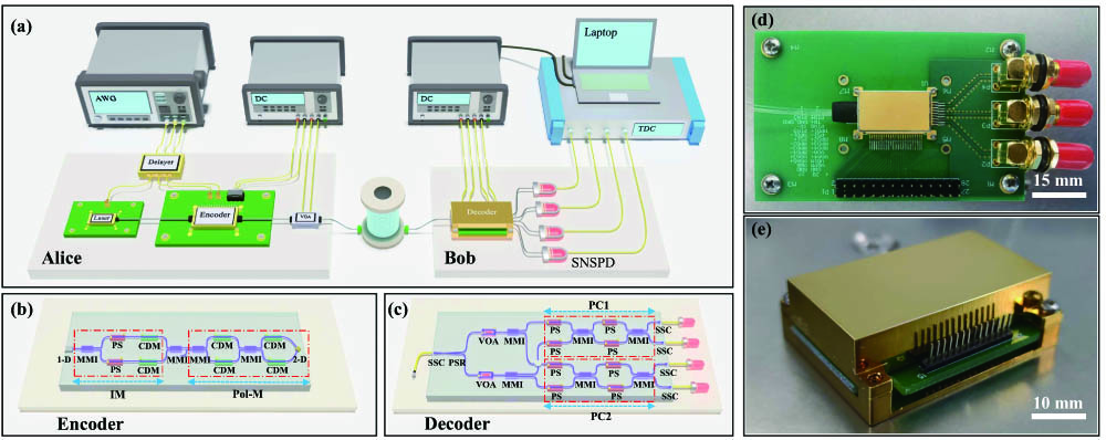
Fig. 1. Silicon-based QKD system. (a) Schematic of the QKD setup. Laser, laser diode; Encoder, silicon chip integrating an intensity modulator and a polarization state modulator; VOA, variable optical attenuator; Decoder, polarization state demodulation chip; SNSPD, superconducting nanowire single photon detector; TDC, time digital converter; AWG, arbitrary waveform generator; DC, programmable DC power supply; Delayer, home-made time delay generator. (b) Schematic of the encoder. MMI, multimode interferometer; PS, thermo-phase shifter; CDM, carrier-depletion modulator; 1-D, one-dimensional grating coupler; 2-D, two-dimensional grating coupler; IM, intensity modulator; Pol-M, polarization modulator. (c) Schematic of the decoder. SSC, spot-size converter; PSR, polarization splitter-rotator. (d) Picture of the packaged encoder chip soldered to the external control board. (e) Picture of the packaged decoder chip soldered to the external control board.
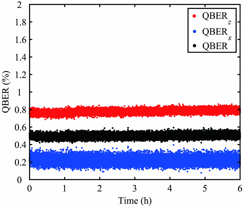
Fig. 2. QBER on Z ( X ) Z ( X )
Fig. 3. QBER measurements for a 50 km fiber channel over 2.4 h operation. During the measurement process, an increased voltage at a step of 1 V is applied to the fiber scrambler every 5 min to mimic the polarization drift of the fiber channel. The black (red) and green (blue) dots represent the measured QBER x QBER z QBER x = 0.86 % ± 0.17 % QBER z 0.84 % ± 0.13 %
Fig. 4. Secure key rates with different transmission loss. The blue line represents the simulation results based on our experimental parameters, and the red dots represent the experimental results.
Fig. 5. The way Alice sends a synchronization string is shown. The red and blue squares represent single bits of the synchronization and random string, respectively. (a) Qubit4Sync. Alice first sends a synchronous string of length L L L M L N f = ( M + 1 ) L
Fig. 6. Schematic of reverse-processing s B s B L M + 1 ( M + 1 ) × L s i B
|
Table 1. Overview of Experimental Parameters and Performances for Different Distancesa

Set citation alerts for the article
Please enter your email address
© Copyright 2018-2021 | Chinese Laser Press. All Rights Reserved 沪ICP备15018463号-20