
Colin Danson, David Neely, and David Hillier. Pulse fidelity in ultra-high-power (petawatt class) laser systems[J]. High Power Laser Science and Engineering, 2014, 2(4): 04000e34
- High Power Laser Science and Engineering
- Vol. 2, Issue 4, 04000e34 (2014)
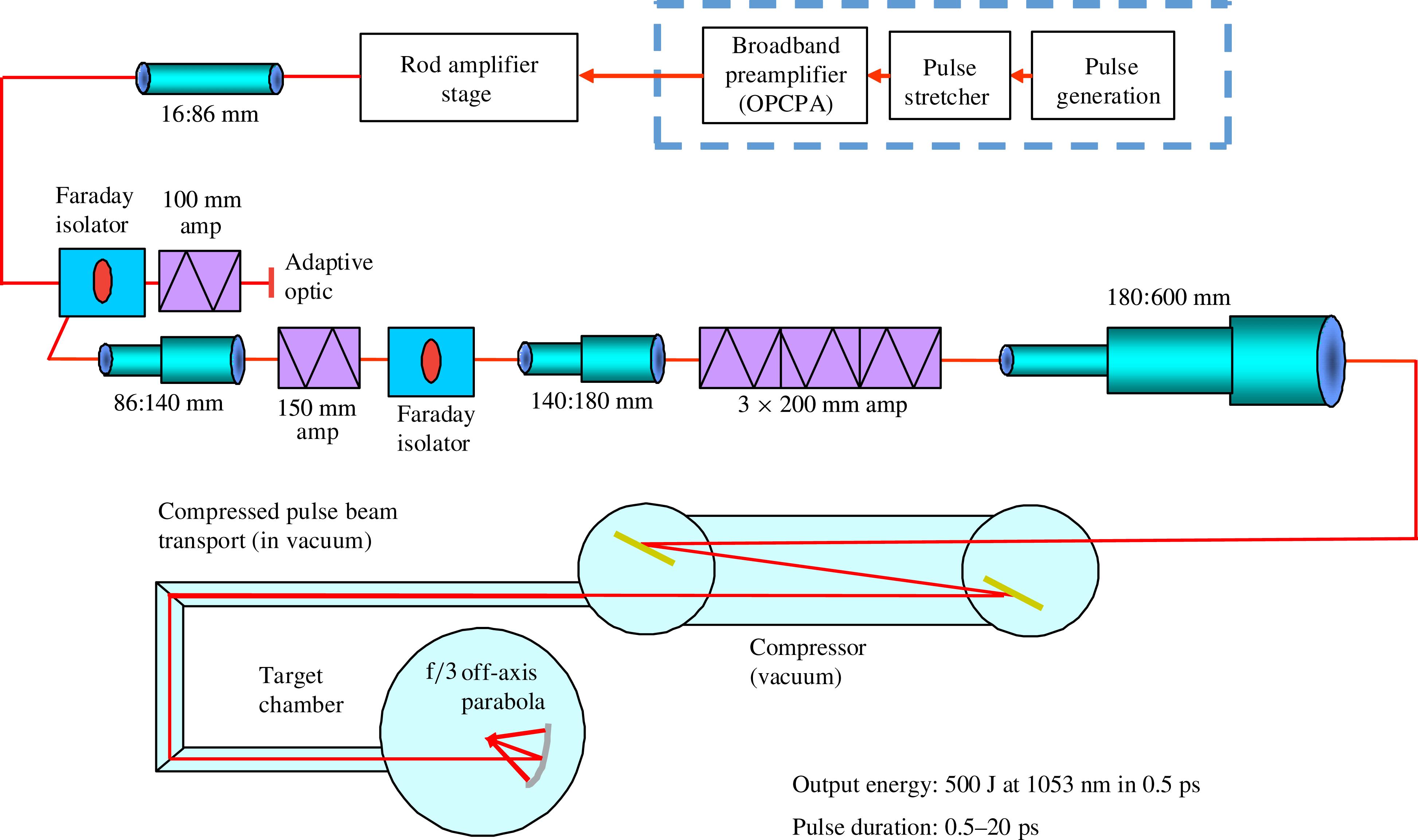
Fig. 1. Layout of the Orion/Vulcan petawatt laser systems.
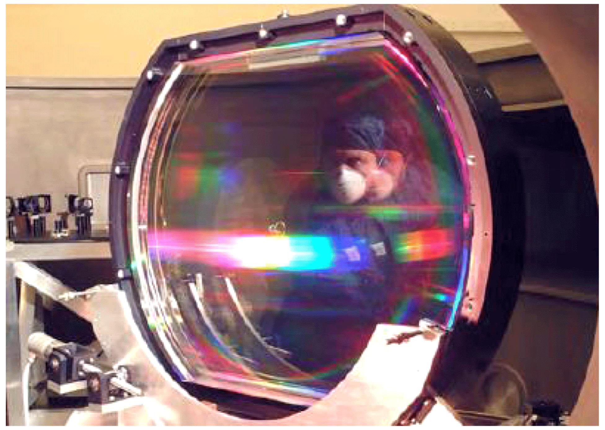
Fig. 2. One of the 940 mm aperture compressor gratings installed on the Vulcan Petawatt beamline.
Fig. 3. (a) The Orion petawatt output bandwidth. (b) The Orion output temporal profile demonstrating <500 fs pulsewidth.
Fig. 4. Prototype adaptive mirror as deployed on Vulcan Petawatt.
Fig. 5. Vulcan Petawatt beam focal spot scan to target using joule-level pulses.
Fig. 6. (a) Orion uncorrected petawatt output focal profile. (b) Orion corrected petawatt output focal profile. (c) Soft x-ray emission from an Orion target shot demonstrating an  X-ray spot size. (d) Optical self-emission from an Orion target shot indicating a focal spot profile of
  .
.
X-ray spot size. (d) Optical self-emission from an Orion target shot indicating a focal spot profile of . Fig. 7. Astra-Gemini laser system.
Fig. 8. Astra-Gemini target chamber.
Fig. 9. Comparison of the frequency conversion efficiencies of a 2 and a 4 mm Type I KDP frequency-doubling crystal.
Fig. 10. Schematic of the second harmonic option on Orion.
Fig. 11. Contrast measurements on Orion of the fundamental and second harmonic.
Fig. 12. Scheme to introduce an additional picosecond stretcher.
Fig. 13. Schematic of the picosecond stretcher used on Vulcan for contrast enhancement.
Fig. 14. Measurement of contrast improvement on the Orion facility from introducing the high-contrast front-end system.
Fig. 15. Contrast measurements on the Astra-Gemini system with the original gratings in blue and the replacement gratings in red.
Fig. 16. Cartoon of plasma mirror operation.
Fig. 17. Typical data from the Ziener plasma mirror experiments.
Fig. 18. Double plasma mirror system on Astra-Gemini.

Set citation alerts for the article
Please enter your email address
© Copyright 2018-2021 | Chinese Laser Press. All Rights Reserved 沪ICP备15018463号-20