
Colin Danson, David Neely, and David Hillier. Pulse fidelity in ultra-high-power (petawatt class) laser systems[J]. High Power Laser Science and Engineering, 2014, 2(4): 04000e34
- High Power Laser Science and Engineering
- Vol. 2, Issue 4, 04000e34 (2014)
Abstract
1. Systems description
The facilities highlighted within this paper are operated at AWE, Aldermaston, UK and the Central Laser Facility (CLF), STFC (Science and Technology Facilities Council) Rutherford Appleton Laboratory (RAL), UK and have the following system parameters:
2. Petawatt generation delivering focused intensities of  W cm
W cm
Short-pulse capabilities on all these systems are based on the technique of chirped pulse amplification (CPA)[
Sign up for High Power Laser Science and Engineering TOC. Get the latest issue of High Power Laser Science and Engineering delivered right to you!Sign up now
2.1. Orion & Vulcan ultra-high-power delivery
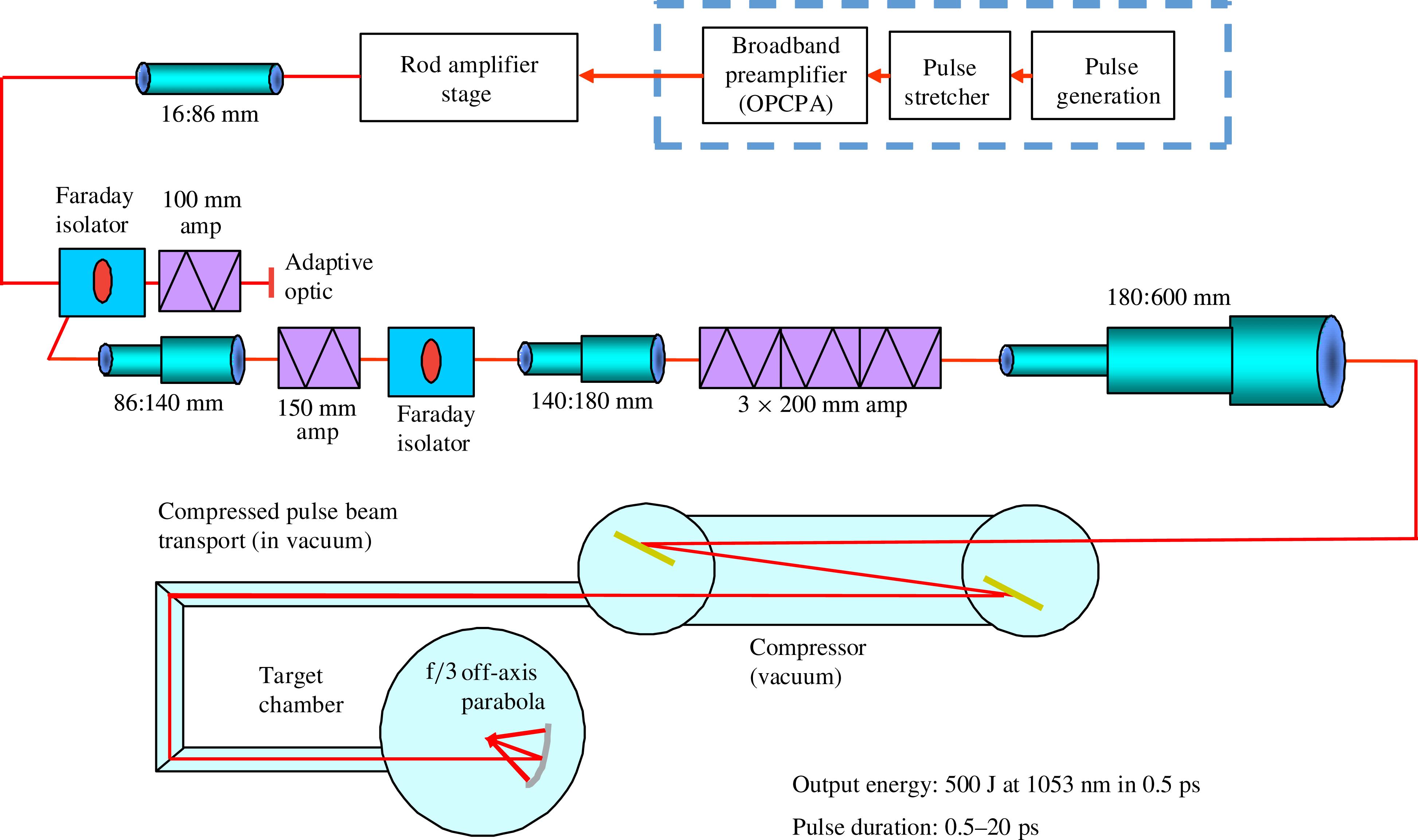
The Orion and Vulcan short-pulse petawatt beamlines are based on the master oscillator–power amplifier (MOPA) architecture (see Figure  double-passed
 , 150 and 200 mm
  aperture). An adaptive optic mirror, a critical component in generating the ultra-high intensities to target, is positioned as the reflecting mirror between the double passes of the 100 mm disc amplifier. Feedback is provided from a Hartmann sensor positioned in the output diagnostic package.
Following the disc amplifier stages, a beam at the 700 J level is expanded to 600 mm in diameter and compressed in a single-pass geometry using a pair of gold-coated diffraction gratings (with 1480 lines mm ) separated by 13 m and housed in a large vacuum chamber. The resulting 500 J, 0.5 ps beams are then propagated to target in vacuum and focused using an F/3, 1.8 m focal length off-axis parabola (OAP).
There is now vast experience and understanding of the generation of petawatt pulses to target, as detailed in [
Having generated the petawatt beam, the use of adaptive optics holds the key to achieving the spot size and pulse duration required for irradiances on target > W cm
W cm . In CLF tests, an adaptive optics system achieved a cycle rate of
  8 Hz with correction to 0.45
  . At the time that Vulcan Petawatt was being developed there were no commercial solutions to large aperture wavefront correction; therefore, an in-house prototype ‘
 bimorph’ mirror was developed at RAL (see Figure
The final output beam to target was found to have residual astigmatism which could be compensated for by optimizing the focal spot using the offset and tilt of the OAP. The spots were first optimized using the Vulcan narrowband CW alignment beam and then optimized at the joule level using rod amplifier shots. Focal spot diameters of  were generated to target (see Figure
On full-energy shots, the focal spot on target was monitored using X-ray pinhole camera imaging, resulting in focal spot sizes of  FWHM (the X-ray image is likely to be larger than the optical image due to plasma expansion), giving focused intensities to target on high-energy shots of
  W cm
W cm .
.
On Orion, a commercial wavefront corrector (Imagine Optics/CILAS) could be deployed. With a nominally flat mirror in the deformable mirror location an aberration of 2.5  peak-to-valley (mostly astigmatism) could be observed. With the 63-element monomorph deformable mirror in place this is corrected to <0.5
  peak-to-valley. As with Vulcan, the optimization to target is done using the final focusing OAP. The optical images, taken in the output beam diagnostics prior to the compressors and shown in Figures
To see the image on higher-energy shots to target, a combination of X-ray pinhole imaging and optical imaging of the plasma self-emission was used. Figure  FWHM with a limiting resolution of
  . The streaked optical transition radiation (OTR) emission gives a central image size of
  FWHM (shown in Figure
  W cm
W cm .
.
2.2. Astra-Gemini ultra-high-power delivery
The Astra-Gemini system has a MOPA architecture. The seed pulses are generated from an ultra-short-pulse oscillator that provides low-energy, high-quality pulses of around 12 fs duration. These are stretched to  7 ps in a glass block before being amplified to millijoule energies in a kHz repetition rate preamplifier. Individual pulses are then selected by a fast Pockels cell at a repetition rate of 10 Hz. A much greater stretch is then applied, using a standard grating-based pulse stretcher. The pulses are stretched to
  1 ns and then amplified in a series of Ti:Sapphire crystals that are pumped by pulses of green light from another laser. The infrared beam is sent through each crystal several times to increase efficiency. As the energy in the beam increases, both the beam size and the crystals are made larger in successive amplifiers to keep the intensity of the light below the level where damage will occur.
The Astra-Gemini output amplifiers (see Figure
Laser output energies of 25 J are delivered with around 60 J of pump energy, in good agreement with the modelling. At this energy, assuming a transmission efficiency of 60% in the compressor (which would be lower than average) the energy reaching the target area is 15 J.
The main optics of the compressor are the two gratings and a plane mirror. The smaller grating is 320 mm by 205 mm, and the larger is 265 mm by 420 mm. Both are holographically generated with 1480 grooves per millimetre, and coated with gold. The plane mirror is coated with protected silver for increased reflectivity and damage resistance. The output bandwidth of Astra-Gemini is  35 nm, which overfills the height of the second grating after dispersion by the first grating. The compressor is therefore operated in double pass, so the spatial dispersion of the beam in the first pass is reversed in the second.
The compressed pulse is steered to the final mirror, which sends the beam downwards into a vacuum pipe connected to the interaction chamber. Each beam will deliver 15 J to target in a pulse of 30 fs (i.e., a peak power of 0.5 PW). In the Gemini target chamber, shown in Figure  W cm
W cm can be achieved on target.
3.  operation
The first experiments to demonstrate the feasibility of contrast enhancement using second harmonic generation (SHG) were conducted at small aperture and low energy ( 1 J) at the Centre for Ultrafast Optical Science, University of Michigan by Gerard Mourou’s group[
 from a Type I KDP crystal. The Queneuille work uses SHG on a terawatt laser system to demonstrate an intensity contrast of
  , making possible, for the first time, the study of laser–matter interactions in the ultra-high-intensity, high-contrast regime.
First large aperture (100 mm) trials were carried out on the Vulcan facility[ and 2
and 2 outputs orthogonally polarized such that they can be separated. The experiments showed (see Figure
  and the optimum conversion efficiency for a 2 mm thick crystal is at an intensity greater than 250 GW cm
 with efficiencies of
  60%. These experiments also demonstrated that at higher energies the focal spot would break up, drastically reducing the delivered focused intensity.
The frequency-doubling experiments at large aperture on Vulcan showed that a 2 mm Type I KDP crystal was the optimal choice. It was anticipated, and subsequently demonstrated, that  W cm
W cm could be delivered to target in a frequency-doubled beam, with a much enhanced contrast ratio, opening up new plasma physics experiments.
The first frequency-doubling contrast enhancement experiments to be carried out at AWE were conducted on the HELEN facility in 2006 using 200 mm diameter, 2 mm thick Type I KDP. Although no quantitative contrast measurements were made, experimental data from buried-layer experiments suggests a greatly reduced pre-pulse[ at pulse durations of 0.5 and 2 ps, with delivered target intensities of
  W cm
W cm .
.
Following the early HELEN experiments, Orion was designed from the outset to include the option of frequency doubling on one of the short-pulse petawatt beamlines. The maximum aperture crystal that could be obtained commercially was 300 mm with 3 mm thick Type I KDP. As the output of the Orion petawatt beamline is  600 mm this meant that the beam diameter had to be reduced by a factor of two. A schematic of the second harmonic option as installed on Orion is shown in Figure
Figure  chamber on the right-hand side. A mirror then directs it in to the 320 mm aperture crystal. There follow three
  reflective mirrors and a parabola which reject the residual 1053 nm light and propagate only the 527 nm, frequency-doubled light to target. This option delivers
  J at the second harmonic (200 TW) with a 70% conversion efficiency. This can be focused down to a spot delivering
  W cm
W cm [
[
The temporal contrast after compression was measured in the first harmonic from a leak through from the first mirror after the compressor. In the second harmonic it is measured from a leak through the second mirror after the frequency-doubling crystal. By concatenating photodiode (Newport 818-21A) traces from multiple shots with different attenuation levels, the temporal contrast over a large dynamic range can be measured, as shown in Figure  , about 3 ns before the main pulse, which is due to parametric fluorescence in the OPCPA. When the frequency-doubling option is used, a large improvement is observed, generating a contrast to target of
  .
.
In both measurements, biased silicon photodiodes were used. To achieve sufficient dynamic range the photodiodes required extensive baffling, spectral filtering, and shielding to prevent any stray reflections or scattered light within the diagnostics enclosure swamping the signal. These measurements were all performed with no protection in front of the photodiodes (water cells, etc.), which shortened their life and that of some of the optics in the diagnostics line significantly.
4. High-contrast front-end
The concept of using an OPCPA system as a seed for the front-end of a high-power Nd:glass laser system was first proposed in Ref. [ (this contrast level is still far better than that generated when using a traditional Nd:glass regenerative amplifier, where levels of
  have been measured[
 have been measured[
Itantini
An alternative approach first developed for Omega EP[
The initial seed pulses of 200 fs duration are generated from a commercial Ti:Sapphire oscillator. These pulses are then stretched to 3 ps and amplified in a single-stage OPCPA to take the pulses from 10 pJ to  . A schematic of the picosecond stretch and amplification scheme is shown in Figure
In this scheme, a common seed is used for both the signal and pump pulses, thus ensuring they are optically synchronized. The pump seed pulse is fed into the regenerative amplifier and then frequency-doubled to generate pulses of  to pump the BBO crystal. The regenerative amplifier uses Nd:YLF as the gain medium, producing gain narrowing as the pulse is amplified, increasing the pulse duration to
  10 ps. A stretcher in the signal beam enables pulse length matching between the two pulses and a dog-leg timing adjuster ensures synchronization.
Following picosecond amplification, the pulse is stretched to the nanosecond regime before being amplified in two further OPCPA stages and then injected into the Nd:Glass amplifiers. This increased seed energy has led to an improvement of the nanosecond ASE contrast intensity to  of the main pulse, without degrading the output performance of the Vulcan Petawatt system.
Following the successful demonstration of the high-contrast front-end system on Vulcan, a very similar configuration was installed on the Orion facility. This also demonstrated a nanosecond ASE contrast improvement by  2 orders of magnitude. Figure
5. Optics fidelity
Typically, in Ti:Sapphire-based petawatt class laser systems there is a ‘coherent’ contrast feature that frequently appears as an exponentially-rising pedestal within a few tens of picoseconds of the compressed pulse. Contrast measurements[
New higher-quality gratings were installed in the Astra-Gemini pulse stretcher. The new gratings are etched directly into the fused silica substrates, rather than being formed in a photoresist layer. The contrast was measured both before and after the stretcher gratings were replaced and the results shown in Figure
The etching process may reduce the roughness of the grating surface, giving lower scatter and leading to the observed improvement in contrast. In the ten or more years since the original gratings were made, the technology of grating production has advanced in response to the requirements for high-energy CPA lasers such that gratings made today undoubtedly have better quality.
6. Plasma mirror operation
The use of plasma mirrors close to the target interaction is a technique that can be used to suppress unwanted pre-pulses[
In an experiment at the CLF[ . The specular reflectivity was measured for intensities on target between
  and
and  W cm
W cm .
.
The target was moved after each shot. The intensity on target was varied either by moving the target out of focus (z-scan) or by decreasing the laser energy with a constant focal spot size. A typical result from the paper, as shown in Figure  in this case) and at intensities on the substrate of
  –
– W cm
W cm . For intensities above mid
  W cm
W cm the specular reflectivity decreases again, to values of only a few percent. The drop-off in specular reflectivity has been attributed to an increase in non-specular reflectivity (scatter, absorption or diffuse reflectivity at the plasma surface).
The relative merits of using ‘s’ or ‘p’ polarization have been discussed and verified experimentally in many individual publications. As we often use plasma mirrors at large angles, it is observed that good reflectivities can be obtained when using the ‘s’ polarization but efficiencies drop off when using the ‘p’ polarization, due to higher absorption of the laser light. A more complete characterization of plasma mirrors, both experimentally and theoretically, can be found in the paper by researchers at the CEA Saclay[
During the past few years, the routine use of plasma mirrors on Astra-Gemini has moved from being a research project to a properly engineered capability. A system has been installed in the Astra-Gemini target chamber consisting of a 10  2 cm plasma mirror capable of delivering 100 shots driven by a motorized stage before needing to be changed, as shown in Figure
The system is a folded geometry for compactness and consists of two parabolic mirrors which allow an enhanced contrast collimated beam to be delivered to the final focusing optic within the target chamber. A pair of by-pass optics can be inserted into the system for alignment and experimental set-up.
The contrast improvement from employing the double plasma mirror could not be absolutely measured owing to the use of an autocorrelator which had a dynamic range limit of  . The real contrast is believed to be
  at 1 ns, giving a pre-pulse free relativistic interaction to within 2 ps of the peak of the main interaction pulse.
7. Discussion of contrast enhancement
The techniques discussed can be used together to enhance the contrast further. For instance, the  contrast enhancement has been used on Orion with the high-contrast front-end. A contrast ratio of
  –
– is anticipated, but at the time of writing this had not been measured. The plasma mirror technique has also been used on Vulcan in tandem with its high-contrast front-end operation.
In the early 1990s, as the first CPA systems were coming on line, contrast was not the highest priority and  was seen as the state of the art. When this was first aired, a useful visualization was that this ratio was the same as the ratio of the size of a grain of sand to the height of the Eiffel tower. Having recently measured contrast ratios of
  it has been pointed out that this is now the same ratio as the same grain of sand but now to the distance to the Sun (with
  being the ratio of a grain of sand to the distance to Alpha Centuari!!!).
8. Conclusion
In the twenty years or so of development of ultra-high-power laser facilities to the petawatt level there have been dramatic improvements in the pulse fidelity delivered to target, critical in achieving the highest focused intensities and the highest possible contrast. This paper has summarized how these developments have been implemented on the petawatt class laser facilities based in the UK which are currently open for access to the academic community: Orion at AWE, Aldermaston and Vulcan & Astra-Gemini at the CLF, STFC RAL.
References
[5] I. Musgrave, A. Boyle, D. Carroll, R. Clarke, R. Heathcote, M. Galimberti, J. Green, D. Neely, M. Notley, B. Parry, W. Shaikh, T. Winstone, D. Pepler, A. Kidd, C. Hernandez-Gomez, J. Collier. Proc. SPIE, 8780(2013).
[6] C. J. Hooker, S. Blake, O. Chekhlov, R. J. Clarke, J. L. Collier, E. J. Divall, K. Ertel, P. S. Foster, S. J. Hawkes, P. Holligan, B. Landowski, B. J. Lester, D. Neely, B. Parry, R. Pattathil, M. Streeter, B. E. Wyborn. Proceedings of CLEO JThB2(2008).
[7] D. Strickland, G. Mourou. Opt. Commun., 56, 219(1985).
[9] A. Dubietis, G. Jonusauskas, A. Piskarskas. Opt. Commun., 88, 437(1992).
[10] I. N. Ross, P. Matousek, M. Towrie, A. J. Langley, J. L. Collier. Opt. Commun., 144, 125(1997).
[16] C. R. D. Brown, D. J. Hoarty, S. F. James, D. Swatton, S. J. Hughes, J. W. Morton, T. M. Guymer, M. P. Hill, D. A. Chapman, J. E. Andrew, A. J. Comley, R. Shepherd, J. Dunn, H. Chen, M. Schneider, G. Brown, P. Beiersdorfer, J. Emig. Phys. Rev. Lett., 106(2011).
[25] J. Itatani, J. Faure, M. Nantel, G. Mourou, S. Watanabe. Opt. Commun., 148, 70(1998).
[26] M. P. Kalashnikov, E. Risse, H. Schönnagel, W. Sandner. Opt. Lett., 30, 923(2005).
[27] D. Homoelle, A. L. Gaeta, V. Yanovsky, G. Mourou. Opt. Lett., 27, 1646(2002).
[31] C. Dorrer, I. A. Begishev, A. V. Okishev, J. D. Zuegel. Opt. Lett., 32, 2143(2007).
[34] H. C. Kapteyn, M. M. Murnane, A. Szoke, R. W. Falcone. Opt. Lett., 16, 490(1993).
[35] D. M. Gold. Opt. Lett., 19, 2006(1994).
[36] A. Tien, M. Nantel, G. Mourou, D. Kaplan, M. Bouvier. Opt. Lett., 22, 1559(1997).

Set citation alerts for the article
Please enter your email address
© Copyright 2018-2021 | Chinese Laser Press. All Rights Reserved 沪ICP备15018463号-20