• Photonics Research
  • Vol. 9, Issue 3, 331 (2021)
Hui Yang1, Zhenwei Xie1、2、4, Guanhai Li3, Kai Ou3, Feilong Yu3, Hairong He1, Hong Wang2, and Xiaocong Yuan1、*
Author Affiliations
  • 1Nanophotonics Research Center, Shenzhen Key Laboratory of Microscale Optical Information Technology, Institute of Microscale Optoelectronics, Shenzhen University, Shenzhen 518060, China
  • 2School of Electrical and Electronic Engineering, Nanyang Technological University, Singapore 639798, Singapore
  • 3National Laboratory for Infrared Physics, Shanghai Institute of Technical Physics, Chinese Academy of Sciences, Shanghai 200083, China
  • 4e-mail: ayst3_1415926@sina.com
  • show less
    DOI: 10.1364/PRJ.411503 Cite this Article Set citation alerts
    Hui Yang, Zhenwei Xie, Guanhai Li, Kai Ou, Feilong Yu, Hairong He, Hong Wang, Xiaocong Yuan. All-dielectric metasurface for fully resolving arbitrary beams on a higher-order Poincaré sphere[J]. Photonics Research, 2021, 9(3): 331 Copy Citation Text show less
    (a) Schematic of the metadevice capable of fully resolving the beams on an arbitrary HOPS. Inset: Side view of the meta-atom, which consists of an all-silicon nanoblock with an elliptical cross section. The Dirac symbols |R⟩, |L⟩, |X⟩, and |D⟩ represent the focusing effects of the four predesigned metalenses for right-handed circularly polarized (RCP), left-handed circularly polarized (LCP), x-linearly polarized (XLP), and diagonal linearly polarized (DLP) light, respectively. The symbols lL=d and lR=d (d=−1, 0, +1) represent the generated topological charge numbers of the CP-decoupled focusing vortex generator under LCP and RCP light, respectively. One can see the period along the x- and y-axes P and the height of the meta-atom h. (b) and (c) Illustrations of the two selected HOPSs and some typical polarization state patterns on HOPS0,0 and HOPS1,−1, respectively.
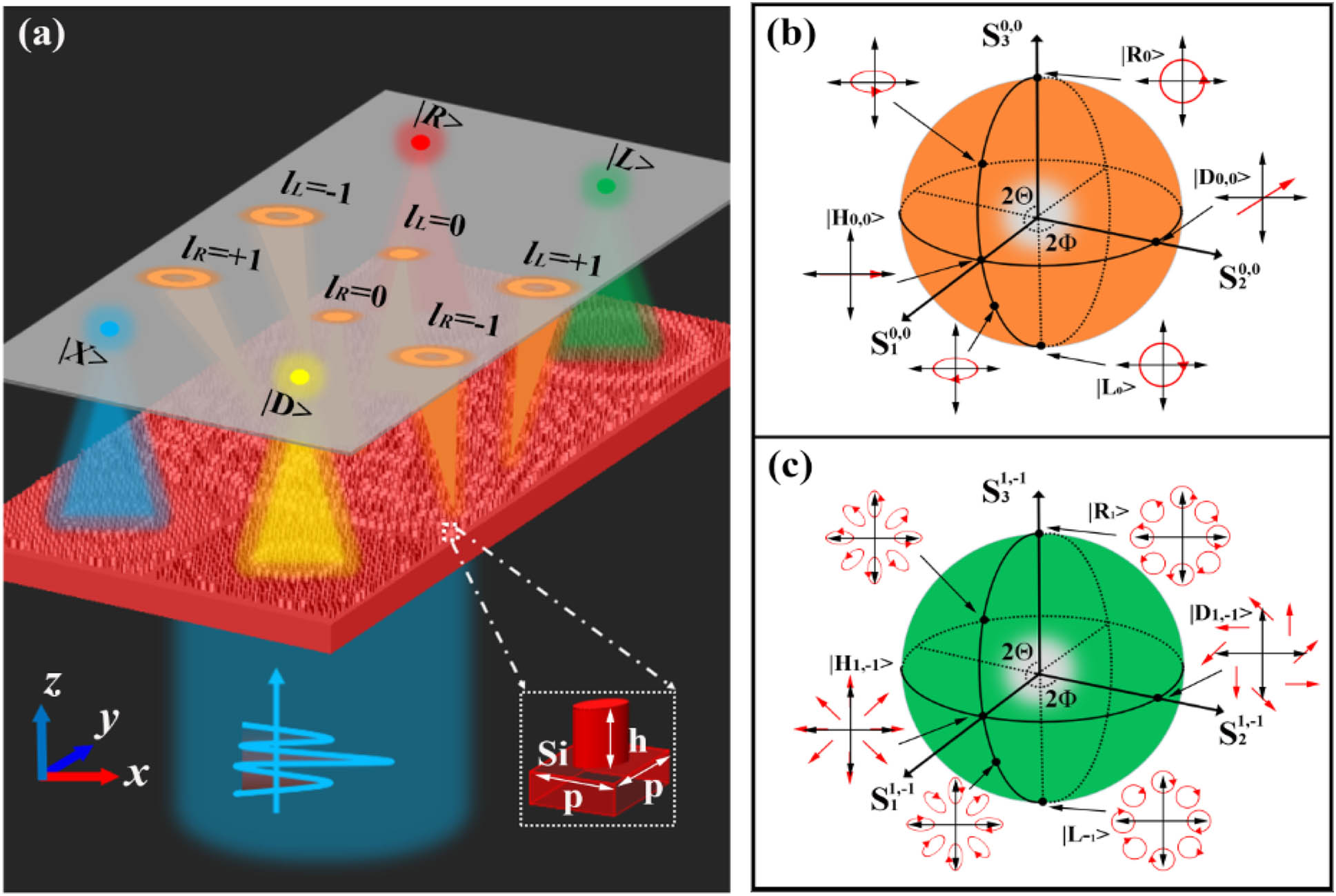
    Fig. 1. (a) Schematic of the metadevice capable of fully resolving the beams on an arbitrary HOPS. Inset: Side view of the meta-atom, which consists of an all-silicon nanoblock with an elliptical cross section. The Dirac symbols |R, |L, |X, and |D represent the focusing effects of the four predesigned metalenses for right-handed circularly polarized (RCP), left-handed circularly polarized (LCP), x-linearly polarized (XLP), and diagonal linearly polarized (DLP) light, respectively. The symbols lL=d and lR=d (d=1, 0, +1) represent the generated topological charge numbers of the CP-decoupled focusing vortex generator under LCP and RCP light, respectively. One can see the period along the x- and y-axes P and the height of the meta-atom h. (b) and (c) Illustrations of the two selected HOPSs and some typical polarization state patterns on HOPS0,0 and HOPS1,1, respectively.
    Simulated intensity profiles of the CP-decoupled focusing vortex generator with four incident beams on HOPS0,0. The four incident beams are (a) RCP, (b) LCP, (c) XLP, and (d) DLP. They are represented by Dirac symbols as |R0,0⟩, |L0,0⟩, |X0,0⟩, and |D0,0⟩, respectively.
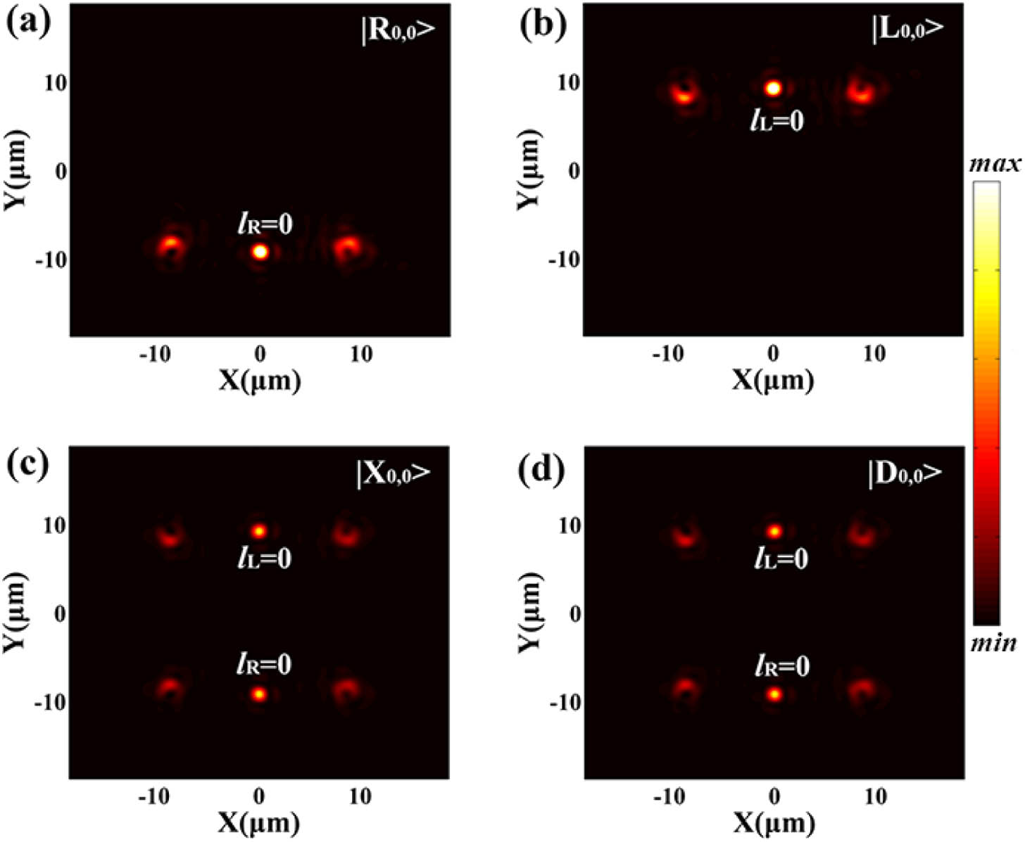
    Fig. 2. Simulated intensity profiles of the CP-decoupled focusing vortex generator with four incident beams on HOPS0,0. The four incident beams are (a) RCP, (b) LCP, (c) XLP, and (d) DLP. They are represented by Dirac symbols as |R0,0, |L0,0, |X0,0, and |D0,0, respectively.
    Fully resolved beams on HOPS0,0 by the designed metadevice, which is composed of a CP-decoupled focusing vortex generator and four elaborately designed distinctive metalenses. (a)–(d) Simulated intensity (|E|2) profiles of the metadevice for incident light with four polarization states: |R0,0⟩, |L0,0⟩, |X0,0⟩, and |D0,0⟩, respectively. (e)–(h) Corresponding 1D cross sections of the simulated intensity profiles along the x axis at y=±8 μm, respectively.
    Fig. 3. Fully resolved beams on HOPS0,0 by the designed metadevice, which is composed of a CP-decoupled focusing vortex generator and four elaborately designed distinctive metalenses. (a)–(d) Simulated intensity (|E|2) profiles of the metadevice for incident light with four polarization states: |R0,0, |L0,0, |X0,0, and |D0,0, respectively. (e)–(h) Corresponding 1D cross sections of the simulated intensity profiles along the x axis at y=±8  μm, respectively.
    Fully resolved beams on HOPS1,−1. (a)–(d) Simulated intensity (|E|2) profiles of the metadevice for incident light with four polarization states: |R1,−1⟩, |L1,−1⟩, |X1,−1⟩, and |D1,−1⟩, respectively. (e)–(h) Corresponding 1D cross sections of the simulated intensity profiles along the x axis at y=±8 μm, respectively.
    Fig. 4. Fully resolved beams on HOPS1,1. (a)–(d) Simulated intensity (|E|2) profiles of the metadevice for incident light with four polarization states: |R1,1, |L1,1, |X1,1, and |D1,1, respectively. (e)–(h) Corresponding 1D cross sections of the simulated intensity profiles along the x axis at y=±8  μm, respectively.
    Original (red circles) and reconstructed (blue asterisks) polarization states of beams on the HOPS0,0 (orange sphere) and HOPS1,−1 (green sphere), respectively. Here, we selected eight incident beams as examples: |R⟩, |L⟩, |X⟩, |Y⟩, |D⟩, |A⟩, |EP1⟩, and |EP2⟩. The black and red dashed lines in both HOPSs represent the latitude and longitude lines at S3=0 and S2=0, respectively.
    Fig. 5. Original (red circles) and reconstructed (blue asterisks) polarization states of beams on the HOPS0,0 (orange sphere) and HOPS1,1 (green sphere), respectively. Here, we selected eight incident beams as examples: |R, |L, |X, |Y, |D, |A, |EP1, and |EP2. The black and red dashed lines in both HOPSs represent the latitude and longitude lines at S3=0 and S2=0, respectively.
    (a) and (b) Side and top views of the birefringent meta-atom with elliptical cross-section, which consist of an all-silicon nanoblock. Detailed parameters of the meta-atom are the height h=1000 nm, the length along x-axis a, the length along y-axis b, the lattice constant P=800 nm, and the orientation angle θ. (c) and (d) Phase shift and transmission as functions of meta-atom’s two lengths with x-linearly polarized (XLP) incident light. (e) and (f) Phase shift and transmission as functions of meta-atom’s two lengths with y-linearly polarized (YLP) incident light. To minimize optical coupling between neighboring meta-atoms, only elliptical nanoblocks with lengths (a and b) range from 150 to 700 nm are adopted. Here, the orientation angle of the meta-atom is set as θ=0.
    Fig. 6. (a) and (b) Side and top views of the birefringent meta-atom with elliptical cross-section, which consist of an all-silicon nanoblock. Detailed parameters of the meta-atom are the height h=1000  nm, the length along x-axis a, the length along y-axis b, the lattice constant P=800  nm, and the orientation angle θ. (c) and (d) Phase shift and transmission as functions of meta-atom’s two lengths with x-linearly polarized (XLP) incident light. (e) and (f) Phase shift and transmission as functions of meta-atom’s two lengths with y-linearly polarized (YLP) incident light. To minimize optical coupling between neighboring meta-atoms, only elliptical nanoblocks with lengths (a and b) range from 150 to 700 nm are adopted. Here, the orientation angle of the meta-atom is set as θ=0.
    Selected optimized meta-atoms. (a) and (b) Selected parameter values a and b as functions of phase shift φx and φy. (c) and (d) Transmissions for the selected meta-atoms at XLP and YLP incident lights, respectively.
    Fig. 7. Selected optimized meta-atoms. (a) and (b) Selected parameter values a and b as functions of phase shift φx and φy. (c) and (d) Transmissions for the selected meta-atoms at XLP and YLP incident lights, respectively.
    Simulated intensity profiles of the CP decoupled focusing vortex generator with incident beams on HOPS1,−1. Four incident beams are selected as examples: (a) RCP, (b) LCP, (c) XLP, (d) DLP, and their Jones vectors are represented as |R1,−1⟩, |L1,−1⟩, |X1,−1⟩, |D1,−1⟩, respectively.
    Fig. 8. Simulated intensity profiles of the CP decoupled focusing vortex generator with incident beams on HOPS1,1. Four incident beams are selected as examples: (a) RCP, (b) LCP, (c) XLP, (d) DLP, and their Jones vectors are represented as |R1,1, |L1,1, |X1,1, |D1,1, respectively.
    Simulated intensity profiles of the CP-decoupled focusing vortex generator with incident beams on different HOPSm,n. Incident XLP beams on specific HOPSm,n are selected as examples, and their Jones vectors are represented as |X4,−4⟩, |X2,−2⟩, |X0,0⟩, |X−3,3⟩, |X−2,−4⟩, and |X1,−3⟩, respectively.
    Fig. 9. Simulated intensity profiles of the CP-decoupled focusing vortex generator with incident beams on different HOPSm,n. Incident XLP beams on specific HOPSm,n are selected as examples, and their Jones vectors are represented as |X4,4, |X2,2, |X0,0, |X3,3, |X2,4, and |X1,3, respectively.
    Intensity (|E|2) profiles of the metadevice for incident lights on HOPS0,0 with four different polarization states: (a) y-linearly polarized (YLP); (b) antidiagonal linearly polarized (ALP); (c) elliptically polarized (EP1) with ellipticity +0.5; (d) elliptically polarized (EP2) with ellipticity −0.5.
    Fig. 10. Intensity (|E|2) profiles of the metadevice for incident lights on HOPS0,0 with four different polarization states: (a) y-linearly polarized (YLP); (b) antidiagonal linearly polarized (ALP); (c) elliptically polarized (EP1) with ellipticity +0.5; (d) elliptically polarized (EP2) with ellipticity 0.5.
    Intensity (|E|2) profiles of the metadevice for incident light on HOPS1,−1 with four different vector lights situated at the same locations as those in Fig. 9: (a) y-linearly polarized (YLP, |Y1,−1⟩); (b) antidiagonal linearly polarized (ALP, |A1,−1⟩); (c) elliptically polarized (|EP11,−1⟩) with ellipticity +0.5; (d) elliptically polarized (|EP21,−1⟩) with ellipticity −0.5.
    Fig. 11. Intensity (|E|2) profiles of the metadevice for incident light on HOPS1,1 with four different vector lights situated at the same locations as those in Fig. 9: (a) y-linearly polarized (YLP, |Y1,1); (b) antidiagonal linearly polarized (ALP, |A1,1); (c) elliptically polarized (|EP11,1) with ellipticity +0.5; (d) elliptically polarized (|EP21,1) with ellipticity 0.5.
    (a) Polarization conversion rate of the optimized meta-atom versus incident wavelength. The red and green lines represent the ratio of the LCP and RCP components to the total transmission, respectively. (b) Phase shift of the optimized meta-atom versus rotation angle θ.
    Fig. 12. (a) Polarization conversion rate of the optimized meta-atom versus incident wavelength. The red and green lines represent the ratio of the LCP and RCP components to the total transmission, respectively. (b) Phase shift of the optimized meta-atom versus rotation angle θ.
    Original Stokes Parameters (S00,0,S10,0,S20,0,S30,0)Simulated Intensities (%) (I10,0,I20,0,I30,0,I40,0)Reconstructed Stokes Parameters (Simulated)Error
    (1,0,0,1)(5.261,0.285,3.592,3.645)(1.0000,0.0000,0.0000,0.0000)0
    (1,0,0,−1)(0.286,5.244,3.614,3.600)(1.0000,0.0000,0.0000,−1.0000)0
    (1,1,0,0)(2.661,2.643,6.248,3.576)(1.0000,1.0000,0.0000,0.0000)0
    (1,0,1,0)(2.574,2.961,3.569,6.410)(1.0000,0.0000,1.0000,0.0000)0
    (1,0,−1,0)(2.974,2.568,3.636,0.835)(1.0002,−0.0006,−1.0002,0.0002)0.0003
    (1,−1,0,0)(2.886,2.886,0.958,3.669)(1.0000,−1.0000,0.0000,0.0000)0
    (1,0,0.866,0.5)(3.844,1.695,3.568,6.048)(0.9999,0.0001,0.8662,0.4999)0.0001
    (1,0,0.866,−0.5)(1.356,4.175,3.579,6.025)(0.9999,0.0001,0.8660,−0.5003)0.0001
    Table 1. Reconstructing the Stokes Parameters on HOPS0,0 Using the Metadevice
    Original Stokes Parameters (S01,1,S11,1,S21,1,S31,1)Simulated Intensities (%) (I11,1,I21,1,I31,1,I41,1)Reconstructed Stokes Parameters (Simulated)Error
    (1,0,0,1)(7.792,0.435,5.295,5.405)(1.0000,0.0000,0.0000,0.0000)0
    (1,0,0,−1)(0.434,7.728,5.326,5.326)(1.0000,0.0000,0.0000,−1.0000)0
    (1,1,0,0)(4.410,4.374,2.411,3.032)(1.0000,1.0000,0.0000,0.0000)0
    (1,0,1,0)(4.224,3.970,3.077,2.312)(1.0000,0.0000,1.0000,0.0000)0
    (1,0,−1,0)(4.002,4.193,7.543,8.420)(0.9999,0.0013,−1.0015,0.0000)0.0007
    (1,−1,0,0)(3.816,3.789,8.210,7.700)(1.000,−0.9994,−0.0008,0.0000)0.0004
    (1,0,0.866,0.5)(6.049,2.162,3.369,2.741)(1.0001,−0.0002,0.8663,0.5000)0.0002
    (1,0,0.866,−0.5)(2.177,6.001,7.251,7.992)(0.9998,0.0021,0.8687,−0.4999)0.0012
    Table 2. Reconstructing the Stokes Parameters on HOPS1,1 Using the Metadevice
    Hui Yang, Zhenwei Xie, Guanhai Li, Kai Ou, Feilong Yu, Hairong He, Hong Wang, Xiaocong Yuan. All-dielectric metasurface for fully resolving arbitrary beams on a higher-order Poincaré sphere[J]. Photonics Research, 2021, 9(3): 331
    Download Citation