1Nanophotonics Research Center, Shenzhen Key Laboratory of Microscale Optical Information Technology, Institute of Microscale Optoelectronics, Shenzhen University, Shenzhen 518060, China
2School of Electrical and Electronic Engineering, Nanyang Technological University, Singapore 639798, Singapore
3National Laboratory for Infrared Physics, Shanghai Institute of Technical Physics, Chinese Academy of Sciences, Shanghai 200083, China
Characterizing the amplitude, phase profile, and polarization of optical beams is critical in modern optics. With a series of cascaded optical components, one can accurately resolve the optical singularity and polarization state in traditional polarimetry systems. However, complicated optical setups and bulky configurations inevitably hinder future applications for integration. Here, we demonstrate a metadevice that fully resolves arbitrary beams on a higher-order Poincaré sphere (HOPS) via a single-layer all-silicon metasurface. The device is compact and capable of detecting optical singularities and higher-order Stokes parameters simultaneously through a single intensity measurement. To verify the validity of the proposed metadevice, different beams on and are illuminated on the metadevices. The beams are fully resolved, and the reconstructed higher-order Stokes parameters show good agreement with the original ones. Taking the signal-to-noise ratio into account, the numerical simulations indicate that the design strategy can be extended to fully resolve arbitrary beams on HOPS with order up to 4. Because of the advantages of compact configuration and compatibility with current semiconductor technology, the metadevice will facilitate potential applications in information processing and optical communications.
1. INTRODUCTION
Polarization and phase are two intrinsic characteristics of electromagnetic waves, in which polarization indicates the vectorial nature of an oscillating electric field [1]. In 1892, researchers proposed a geometric representation of polarization states termed a “Poincaré sphere” (PS), which unifies all the fundamental polarizations (circular, linear, and elliptical) that exhibit spatially homogeneous distributions [2]. In such a geometric representation, the polarization states are mapped to the PS’ surface through the Stokes parameters in the sphere’s Cartesian coordinates. This geometric representation is a general tool for polarization-pertinent issues in numerous fields. However, the polarization states represented by a conventional PS are limited to electromagnetic waves with homogeneous polarization. For representing waves with spatially inhomogeneous polarizations (such as vector vortex beams), researchers proposed an extended generalized geometric representation known as a higher-order Poincaré sphere (HOPS) [3–8]. The HOPS incorporates spin angular momentum (SAM) and orbital angular momentum (OAM), describes the evolution of both phase and polarization, and provides a new degree of freedom for manipulating light beams. Recently, because of their intriguing properties, beams on HOPS have attracted extensive attention in optical microscopy [9,10], optical trapping [11,12], quantum information technology [13], and mode division multiplexing in optical communication [14,15].
With the development of complex optical beams and their applications, it is important to simultaneously measure the higher-order Stokes parameters and optical singularities in a compact and reliable manner. However, direct polarization measurement is unavailable because of the lack of phase information in conventional intensity probing schemes. As such, to accurately determine the polarization states in conventional methods, one must implement a series of intensity measurements via dividing the input electromagnetic waves temporally or spatially [16,17]. In particular, for characterizing the inhomogeneous polarization state, the optical singularity associated with angular momentum must be measured as well [3]. In such measurements, complicated optical setups (such as a wave plate, polarizer, and diffractive fork gratings) and bulky configurations are inevitably introduced, hindering the development of integrated optical devices.
Metasurface, ultrathin optical components, which are capable of either replacing traditional bulky optical components or achieving exceptional functionalities, have been considered a major advancement in nano-optics [18]. The components are composed of 2D discrete meta-atoms that can locally modify the light’s property and show unprecedent superiority in wavefront manipulation, thus providing an excellent platform for planar and ultracompact optical devices [19,20]. To date, researchers have demonstrated a variety of ultrathin devices based on metasurfaces, such as metalenses [21–27], vortex beam generators [6,28–30], and holograms [31–34]. Likewise, metasurface-enabled polarimeters, which accurately measure Stokes parameters in a compact configuration with straightforward setups compared with conventional counterparts have also attracted much attention [35–42]. For these devices, researchers accurately resolve the polarization states by retrieving the Stokes parameters via detecting the polarization-dependent intensity response of the metasurfaces. Despite their powerful functionalities and compact sizes, these devices are mostly limited to resolving the polarization states on standard PS. For beams on HOPSs, researchers have simultaneously detected the spin and angular momenta of these beams [43–46]. However, these devices cannot fully resolve the incident beams because they are unable to retrieve the Stokes parameters. Therefore, a compact setup capable of fully resolving beams on HOPSs is highly desirable and to date remains unexplored, to our best knowledge.
Sign up for Photonics Research TOC. Get the latest issue of Photonics Research delivered right to you!Sign up now
In this work, to overcome the aforementioned limitation of current polarimetry systems, we demonstrate a compact all-silicon metadevice that completely resolves arbitrary beams on HOPSs. The metadevice is composed of two main parts that detect the angular momentum and higher-order Stokes parameters, respectively. The former can be accomplished by recognizing solid spots in the helicity-decoupled focusing vortex generator, whereas the latter can be achieved by analyzing intensity contrasts in the four predesigned polarization-dependent metalenses. As a result, researchers can completely resolve incident beams on an arbitrary HOPS via a single measurement, without the need for any additional optical components.
We selected two beams of and to verify the metadevice, and the polarization states are well reconstructed by numerical results. Our design strategy is general and can be extended to fully resolve arbitrary beams on any HOPS.
2. PRINCIPLES OF METASURFACE DESIGN
For a paraxial beam on a HOPS, the Jones vector can be expressed in a form of superposition of two circular polarization bases as where representing two circularly polarized vortexes with topological charges and , respectively. The vectors and represent the unit vectors along the and axes, respectively, and is the azimuthal angle. Therefore, by adopting a proper set of coefficients, any point on a HOPS can be expressed as a superposition of these two circularly polarized vortexes.
For a vector vortex beam on a HOPS, the high-order Stokes parameters in the sphere’s Cartesian coordinates can be derived as where and are the intensity of and , respectively. is the phase difference between the two circularly polarized (CP) vortices. In particular, for the specific case , a HOPS reduces to the standard plane wave PS, and the higher-order Stokes parameters in Eqs. (4)–(7) reduce to the standard plane wave Stokes parameters. As such, to obtain a generalized description of all the beams, we treat the standard PS as a special case of HOPS in the remainder of this paper.
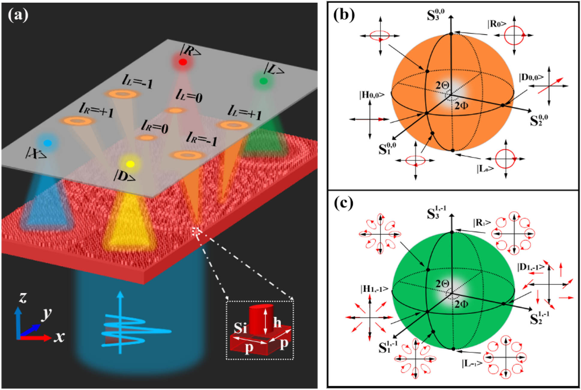
Figure 1.(a) Schematic of the metadevice capable of fully resolving the beams on an arbitrary HOPS. Inset: Side view of the meta-atom, which consists of an all-silicon nanoblock with an elliptical cross section. The Dirac symbols , , , and represent the focusing effects of the four predesigned metalenses for right-handed circularly polarized (RCP), left-handed circularly polarized (LCP), -linearly polarized (XLP), and diagonal linearly polarized (DLP) light, respectively. The symbols and (, 0, ) represent the generated topological charge numbers of the CP-decoupled focusing vortex generator under LCP and RCP light, respectively. One can see the period along the - and -axes and the height of the meta-atom . (b) and (c) Illustrations of the two selected HOPSs and some typical polarization state patterns on and , respectively.
A. Discriminating the Spin and Topological Charge of Incident Beams
To resolve the spin of photon as well as the topological charges and of the incident beam, we designed a CP-decoupled focusing vortex generator. For such a focusing vortex generator, the key issue is to obtain independent phase control under the two CPs. By accommodating both the propagation and geometric phase in the birefringent meta-atoms, one can achieve independent phase control for the two CP light beams (see detailed process in Appendix A). The phase profile of the CP decoupled focusing vortex generator can be expressed as where , , , and are the amplitudes and phase profiles of the th targeted light beam for LCP and RCP, respectively; and are the topological charge number of the th targeted focusing vortex beam for LCP and RCP, respectively; , are the coordinates of the meta-atoms; is the distance from the metasurface to the focal plane; is the focal length for the th targeted focusing vortex beam; and is the azimuthal angle. Here, to obtain equal energy in each channel, we assume a normalized electric field intensity .
By using Eqs. (8)–(10), we arranged the selected meta-atoms to form the CP-decoupled focusing vortex generator. The operating wavelength is , and the focal length is set as . Here, we designated the CP-decoupled focusing vortex generator to generate six focusing vortexes. Three of them are for the LCP state with topological charge , and , respectively, located at (, 8 μm), (0 μm, 8 μm), and (8 μm, 8 μm) in the focal plane. The other three are for the RCP state with topological charge , 0, and , respectively, located at (, ), (0 μm, ), and (8 μm, ), respectively, in the focal plane. One can decompose an arbitrary vector vortex beam on the HOPS into two orthogonal circular beams in the two poles [Eqs. (1)–(3)]. The superposition effect of the angular momentum gives a visualized method for resolving the angular momentum information because annihilation of the angular momentum () results in a solid intensity spot. Therefore, one can use the CP-decoupled focusing vortex generator to fully discriminate the spin and topological charge of the incident beam: focusing spots (when ) manifest at certain positions.
Figure 2.Simulated intensity profiles of the CP-decoupled focusing vortex generator with four incident beams on . The four incident beams are (a) RCP, (b) LCP, (c) XLP, and (d) DLP. They are represented by Dirac symbols as , , , and , respectively.
B. Fully Resolved Beams on by the Designed Metadevice
Figure 3.Fully resolved beams on by the designed metadevice, which is composed of a CP-decoupled focusing vortex generator and four elaborately designed distinctive metalenses. (a)–(d) Simulated intensity () profiles of the metadevice for incident light with four polarization states: , , , and , respectively. (e)–(h) Corresponding 1D cross sections of the simulated intensity profiles along the axis at , respectively.
C. Fully Resolved Beams on by the Designed Metadevice
Figure 4.Fully resolved beams on . (a)–(d) Simulated intensity () profiles of the metadevice for incident light with four polarization states: , , , and , respectively. (e)–(h) Corresponding 1D cross sections of the simulated intensity profiles along the axis at , respectively.
Figure 5.Original (red circles) and reconstructed (blue asterisks) polarization states of beams on the (orange sphere) and (green sphere), respectively. Here, we selected eight incident beams as examples: , , , , , , , and . The black and red dashed lines in both HOPSs represent the latitude and longitude lines at and , respectively.
We also considered the experimental feasibility and potential applications of the proposed all-silicon metadevice. One can fabricate the single-layer all-silicon metadevice with one-step lithography and dry etching. Here, we choose an all-silicon configuration for its simpler fabrication procedure than that of the a-Si on silica substrate configuration (see Appendix E for the detailed comparison of these two configurations). The metadevice has potential applications in polarization-related information processing and optical communications. For example, orthogonally structured light beams such as optical vortex beams and cylindrical vector beams are recent candidates for high-capacity multiplexing optical communication. The metadevice would be important to this process because of its capacity to simultaneously measure the polarization states and optical singularities in a compact and reliable manner.
4. CONCLUSION
In conclusion, we proposed a compact metadevice composed of an all-silicon metasurface, which is capable of completely resolving arbitrary beams on HOPSs. Via a single measurement, one can simultaneously detect the OAM and higher-order Stokes parameters of the incident beams, without the need for additional optical components. To verify the validity of the metadevice, we selected and as examples. Different beams on these two are illuminated on the metadevices, and the reconstructed polarization states show good agreement with the preset ones. Here, these two HOPSs are chosen as proof of concept, and the design strategy can be extended to fully resolve arbitrary beams on HOPS with order up to 4. Diverse applications such as polarization-related information processing and optical communications will be facilitated by the compact configuration of the metadevice and its compatibility with current semiconductor technology.
Acknowledgment
Acknowledgment. H. Wang acknowledges financial support from the Ministry of Education of Singapore (MOE2016-T2-1-052).
APPENDIX A: INDEPENDENT PHASE CONTROL FOR THE TWO CIRCULAR POLARIZATIONS
As demonstrated in previous works, birefringent meta-atoms with both propagation and geometric phase could achieve independent phase control of arbitrary orthogonal states of polarization [31]. To obtain independent phase control of circular polarizations, the phase relationships between the two orthogonal linear and the two orthogonal circular polarizations can be expressed as where , , , and are the phase shifts of -linearly polarized (XLP), -linearly polarized (YLP), LCP, and RCP light, respectively. Therefore, for an arbitrary set of and , one just needs to design the , , and according to the above equations. In other words, we can arbitrarily and independently manipulate the LCP and RCP phases by designing three parameters: the polarized phase , the polarized , and the rotation angle .
The meta-atom capable of providing independent phase control at two orthogonal linearly polarized lights (XLP and YLP) is shown in Figs.?6(a) and 6(b). The birefringent meta-atom consists of an all-silicon elliptical nanoblock (with refractive index ). The detailed parameters of the meta-atom are height , orientation angle , length along -axis , length along -axis , and lattice constant . Figures?6(c)–6(f) show the transmission properties of the meta-atoms, with the simulated phase and transmission amplitude of the meta-atoms as functions of and for the two linear polarizations.
Figure 6.(a) and (b) Side and top views of the birefringent meta-atom with elliptical cross-section, which consist of an all-silicon nanoblock. Detailed parameters of the meta-atom are the height , the length along -axis , the length along -axis , the lattice constant , and the orientation angle . (c) and (d) Phase shift and transmission as functions of meta-atom’s two lengths with -linearly polarized (XLP) incident light. (e) and (f) Phase shift and transmission as functions of meta-atom’s two lengths with -linearly polarized (YLP) incident light. To minimize optical coupling between neighboring meta-atoms, only elliptical nanoblocks with lengths ( and ) range from 150 to 700 nm are adopted. Here, the orientation angle of the meta-atom is set as .
Figure 7.Selected optimized meta-atoms. (a) and (b) Selected parameter values and as functions of phase shift and . (c) and (d) Transmissions for the selected meta-atoms at XLP and YLP incident lights, respectively.
APPENDIX B: DISCRIMINATING THE SPIN AND TOPOLOGICAL CHARGE ON HOPSm,?n
The simulated intensity profiles of the CP decoupled focusing vortex generator under different incident lights on are depicted in Fig.?8. As also depicted in Fig.?8, for the beams on , the solid spot emerges at the specific locations where total angular momentum , which is capable of resolving the topological charge of the incident beams. The detail-resolving process is as follows. Here, a result matrix is adopted to express the topological charges of the generated vortex beams in which the first and second lines represent the topological charges of OAMs generated by LCP and RCP incident lights, respectively. For the case that a solid intensity spot exhibits at , one can conclude that the incident beam is an RCP beam with topological charge (using the relationship ). Similarly, for the case that a solid intensity spot exhibits at , the incident beam is an LCP beam with topological charge . Otherwise, for the case that two solid intensity spots exhibit at both and , the incident beam can be expressed as a combination of the two circularly polarized beams as expressed in Eqs.?(1)–(3) in the main text, with topological charges . Therefore, the designed CP decoupled focusing vortex generator is able to simultaneously resolve the spin of photon and topological charges of the incident beam on .
Figure 8.Simulated intensity profiles of the CP decoupled focusing vortex generator with incident beams on . Four incident beams are selected as examples: (a) RCP, (b) LCP, (c) XLP, (d) DLP, and their Jones vectors are represented as , , , , respectively.
Figure 9.Simulated intensity profiles of the CP-decoupled focusing vortex generator with incident beams on different . Incident XLP beams on specific are selected as examples, and their Jones vectors are represented as , , , , , and , respectively.
APPENDIX C: DETAILED CONFIGURATION OF THE FOUR PREDESIGNED METALENSES
The P-B phase is introduced to the design of the two metalenses for focusing the LCP and RCP incident lights. To fulfill the P-B phase condition, the meta-atom is optimized to function as a half-wave plate, and the polarization conversion rate is also optimized as unity at the working wavelength. The corresponding parameters of the all-silicon meta-atom are , , and . The polarization conversion rate of the meta-atom as a function of the incidence wavelength is depicted in Fig.?12(a). The polarization conversion rate over 99% at 1550?nm indicates the half-wave plate functionality of the meta-atom. In this condition, the meta-atom is able to flip the helicity of the input circularly polarized light and to impart an additional phase shift of on the output light. The phase shift of the meta-atom as a function of rotation angles is plotted in Fig.?12(b). It is obvious that the phase shift and the rotation angle satisfy the P–B phase condition ().
Figure 10.Intensity () profiles of the metadevice for incident lights on with four different polarization states: (a) -linearly polarized (YLP); (b) antidiagonal linearly polarized (ALP); (c) elliptically polarized (EP1) with ellipticity ; (d) elliptically polarized (EP2) with ellipticity .
Figure 11.Intensity () profiles of the metadevice for incident light on with four different vector lights situated at the same locations as those in Fig. 9: (a) -linearly polarized (YLP, ); (b) antidiagonal linearly polarized (ALP, ); (c) elliptically polarized () with ellipticity ; (d) elliptically polarized () with ellipticity .
Figure 12.(a) Polarization conversion rate of the optimized meta-atom versus incident wavelength. The red and green lines represent the ratio of the LCP and RCP components to the total transmission, respectively. (b) Phase shift of the optimized meta-atom versus rotation angle .
For the metalens designed for XLP incident light, the meta-atoms are selected from Figs.?7(c) and 7(d) with minimum error value, where and are the desired and object phase shifts for XLP incident light. Moreover, rotating all the meta-atoms of the metalens for XLP incident light with an angle of 45°, the metalens designed for DLP incident light is achieved.
APPENDIX D: CALCULATING THE HIGHER-ORDER STOKES PARAMETERS
For the vector vortex beam on HOPS, the higher-order Stokes parameters in the sphere’s Cartesian coordinates can be derived as where and are the intensity of and , respectively. is the phase difference between the two circular polarizations. It is clear that the first higher-order Stokes parameter is proportional to the intensity of incident beam , whereas describe the states of polarization. The latter three Stokes parameters can be obtained by respectively measuring the intensities of the three orthonormal polarization basis (, ), (, ), and (, ). Here, the diagonal and antidiagonal polarization basis (, ) corresponds to a rotation of the coordinate system (, ) by with respect to the axis. From the above description of Stokes parameters, it is clear that six polarization components need to be measured to uniquely determine the higher-order Stokes parameters. To simplify the measuring process, a set of four intensity components is introduced, which are capable of determining the Stokes parameters as well. The four intensity components can be derived from Eqs.?(D1)–(D4) as
From Eqs.?(D1)–(D9), there is a linear relationship among the four intensity components () and the higher-order Stokes parameters, which can be described by a device matrix as
However, this is not the final device matrix since the measured intensities are composed of the four polarization components and the background intensities , which consist of transmitted light not modulated by the metasurfaces as well as cross-talk between the different metasurfaces structures. Let us assume there is also a linear relationship among the four polarization components and the background intensities: where is a matrix. Therefore, the relationship between the four polarization components and the measured intensities can be expressed as where represents the intensities measured at the four focusing spots. From Eqs.?(D9)–(D11), the relationship between the higher-order Stokes parameters and the final device matrix can be derived as where represents the Stokes parameters and is a unit matrix. From Eq.?(D12), the final device matrix can be calculated by using . For our designed metadevice, the process to determine the final device matrix is defined as the device calibration process, in which four standard polarization states and their corresponding measured intensities are utilized to calculate the values of final device matrix . By utilizing the simulated intensities in Table?1 and Table?2, the final device matrix for these two cases is calculated as
Then, the designed metadevice is capable of accurately resolving the polarization states by calculating the higher-order Stokes parameters from Eq.?(D11).
APPENDIX E: METADEVICE WITH A-SI ON SILICA SUBSTRATE CONFIGURATION
In the main text, we choose an all-silicon configuration and demonstrate a metadevice for fully resolving arbitrary beams on a HOPS. The all-silicon configuration is selected for its simpler fabrication procedure (requires no additional film deposition during the fabrication procedure) compared with the a-Si on silica substrate configuration. Actually, identical functionality could be achieved for our proposed metadevice with a-Si on silica substrate configuration. To show that, the all-silicon metadevice is replaced with a-Si on silica substrate configuration (the refractive indexes of a-Si and silica are set as 3.7 and 1.46, respectively). The unit cell consists of an a-Si nanoblock placed on a silica substrate. The lattice constant is , and the height of the nanoblock is . With the same strategy, we repeated all the optimization processes and accomplished the same functionalities (resolving different beams on and ). The intensity profiles for the metadevice with a-Si on the silica substrate configuration are identical with those in the main text and hence are not shown here. The corresponding simulated focusing efficiencies and reconstructed Stokes parameters are shown in Tables?3 and 4, respectively. For both cases, the reconstructed Stokes parameters show good agreement with the original ones. From the four tables, one can find that the total intensity of the a-Si on silica substrate configuration is slightly larger than that of the all-silicon configuration. However, the metadevice based on these two configurations shows approximate performance. Therefore, we choose the all-silicon configuration for its simpler fabrication procedure.
Reconstructing the Stokes Parameters on Using the Metadevice with a-Si on Silica Substrate Configuration
Stokes Parameters ()
Simulated Intensities (%) ()
Reconstructed Stokes Parameters (Simulated)
Error
(1,0,0,1)
(8.863,0.635,4.879,4.271)
(1.0000,0.0000,0.0000,0.0000)
0
(1,0,0,?1)
(0.669,8.994,4.392,4.623)
(1.0000,0.0000,0.0000,?1.0000)
0
(1,1,0,0)
(4.925,4.982,7.322,4.342)
(1.0000,1.0000,0.0000,0.0000)
0
(1,0,1,0)
(4.910,4.648,4.576,6.782)
(1.0000,0.0000,1.0000,0.0000)
0
(1,0,?1,0)
(4.623,4.981,4.695,2.113)
(1.0001,?0.0002,?0.9998,0.0001)
0.0002
(1,?1,0,0)
(4.607,4.647,1.950,4.533)
(1.0000,?0.9996,0.0005,?0.0000)
0.0002
(1,0,0.866,0.5)
(2.842,6.760,4.462,6.557)
(1.0000,?0.0000,0.8660,0.5000)
0
(1,0,0.866,?0.5)
(6.939,2.581,4.706,6.381)
(1.0000,0.0001,0.8659,?0.4999)
0.0001
Reconstructing the Stokes Parameters on Using the Metadevice with a-Si on Silica Substrate Configuration
Stokes Parameters ()
Simulated Intensities (%) ()
Reconstructed Stokes Parameters (Simulated)
Error
(1,0,0,1)
(9.628,0.719,5.265,4.607)
(1.0000,0.0000,0.0000,0.0000)
0
(1,0,0,?1)
(0.752,9.763,4.724,4.927)
(1.0000,0.0000,0.0000,?1.0000)
0
(1,1,0,0)
(5.009,5.048,2.773,3.345)
(1.0000,1.0000,0.0000,0.0000)
0
(1,0,1,0)
(5.179,5.240,3.324,2.897)
(1.0000,0.0000,1.0000,0.0000)
0
(1,0,?1,0)
(5.200,5.242,6.667,6.638)
(0.9999,?0.0013,?0.9999,?0.0001)
0.0004
(1,?1,0,0)
(5.370,5.433,7.217,6.190)
(0.9998,?1.0003,?0.0008,?0.0000)
0.0003
(1,0,0.866,0.5)
(7.400,2.979,3.683,3.067)
(1.0000,?0.0004,0.8667,0.5001)
0.0002
(1,0,0.866,?0.5)
(2.980,7.503,6.307,6.468)
(1.0000,0.0003,0.8671,?0.5001)
0.0004
References
[1] M. Born, E. Wolf. Principles of Optics(1999).
[2] R. M. A. Azzam, N. M. Bashara. Ellipsometry and Polarized Light(1977).