
Zhenglong Lei, Jianxiong Shen, Bingwei Li, Heng Zhou, Yanbing Chen. Recognition of Narrow-Gap Edge Welding Seam Based on Autonomous Threshold Value[J]. Acta Optica Sinica, 2018, 38(8): 0815011
- Acta Optica Sinica
- Vol. 38, Issue 8, 0815011 (2018)
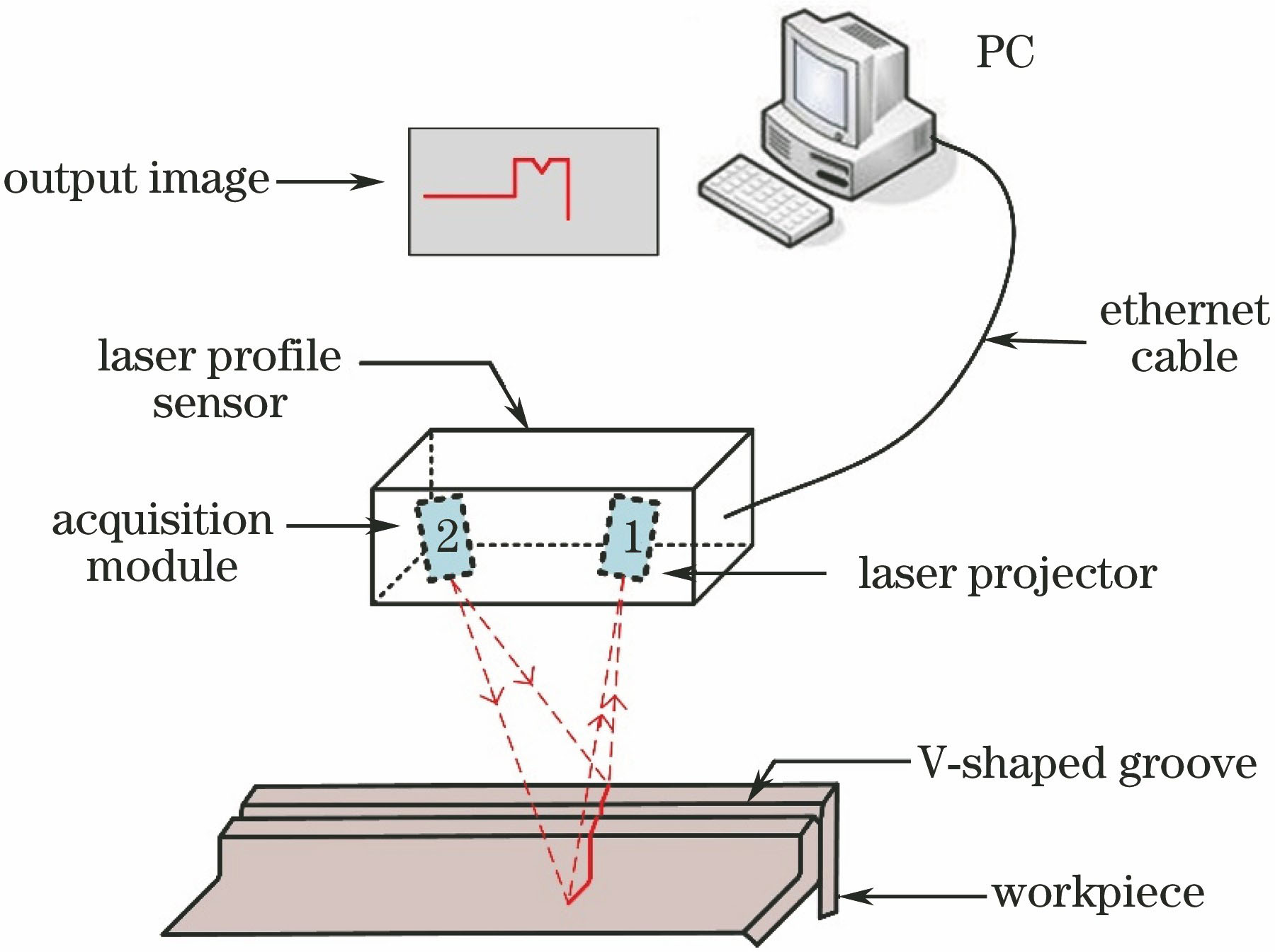
Fig. 1. Laser scanning process of vision sensor system
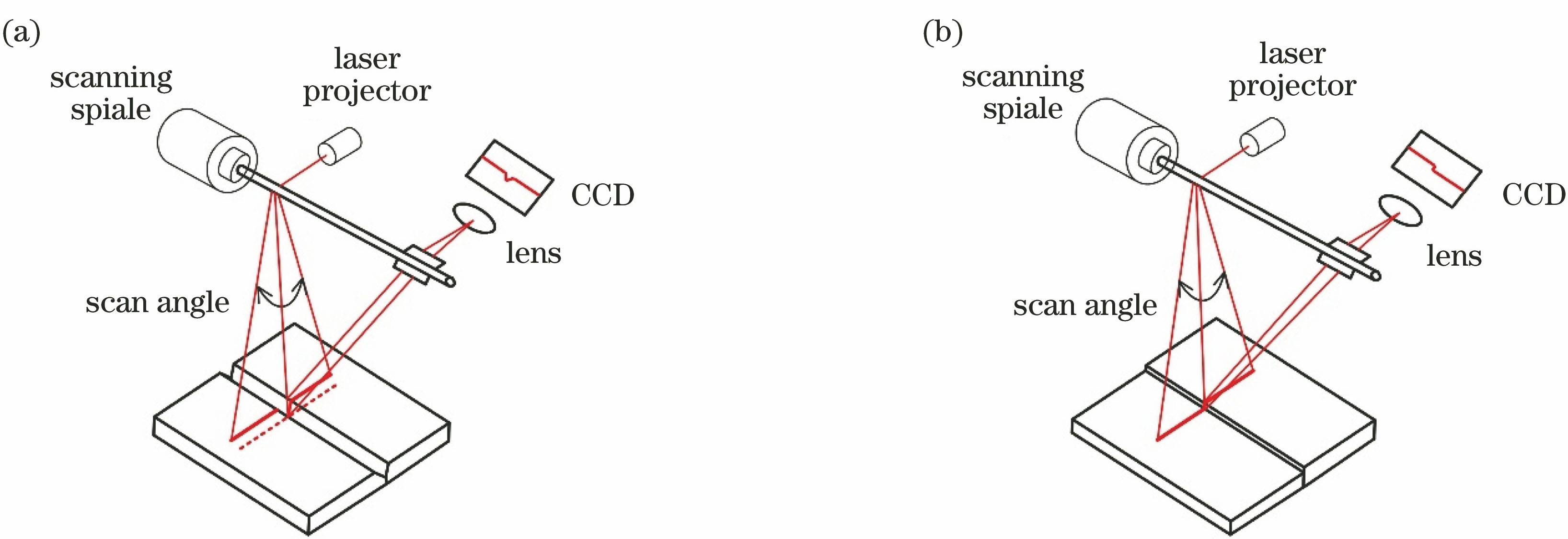
Fig. 2. Seam measurement by optical triangulation with scanning light. (a) V-shaped groove butt joint; (b) butt joint with misalignment
Fig. 3. Comparison of deformation amount under different weld joints. (a) V-shaped groove; (b) with misalignment; (c) small gap less than 0.5 mm and without misalignment
Fig. 4. Original weld seam image captured by vision sensor and its local large map
Fig. 5. Comparison of results using different median filterings. (a)-(c) Results of traditional median filtering; (d)-(f) results of improved median filtering
Fig. 6. V-shaped groove diagram extracted by slope analysis
Fig. 7. Principle diagram of magnifying details method based on threshold
Fig. 8. Curves of intercept (a) without magnifying details and (b) with magnifying details
Fig. 9. Extracted results of narrow-gap feature points (a) without magnifying details and (b) with magnifying details
Fig. 10. Image process and feature extraction
Fig. 11. Experimental results and error curves under different thickness conditions. (a) Thickness is 2 mm; (b) thickness is 3 mm
Fig. 12. Microtopography of weld seam. (a) Symmetric distribution; (b) off center
|
Table 1. Configuration of weldment

Set citation alerts for the article
Please enter your email address
© Copyright 2018-2021 | Chinese Laser Press. All Rights Reserved 沪ICP备15018463号-20