
Haifeng Yao, Xiaolong Ni, Chunyi Chen, Shoufeng Tong, Huilin Jiang, Zhi Liu. Channel Compensation Based on Pulse Laser Propagating in Atmosphere[J]. Acta Optica Sinica, 2018, 38(1): 0101003
- Acta Optica Sinica
- Vol. 38, Issue 1, 0101003 (2018)
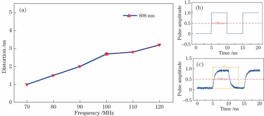
Fig. 1. (a) Variation in waveform distortion with frequency; (b) ideal rectangular pulse; (c) simulated pulse
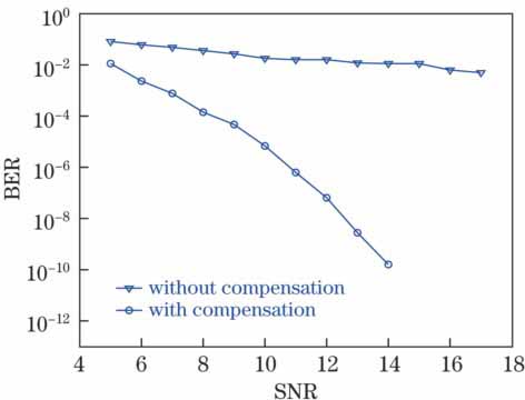
Fig. 2. Simulation diagram of bit error rate
Fig. 3. Field laser transmission experiment. (a) Transmitting terminal; (b) atmosphere channel; (c) receiving terminal
Fig. 4. Processing flow for experimental data
Fig. 5. Co-simulation of ISE and modelsim. (a) Register-transfer level schematic of ISE simulation; (b) result of modelsim simulation; (c) relationship between number of w and mean square error; (d) mean square error of real-time data
Fig. 6. Average time waveform of received light pulse intensity. (a) Time waveform of simulated 100 MHz rectangular pulse; (b) average time waveform of transmitting terminal; (c) average time waveform of rectangular pulse laser signal after passing through atmosphere; (d) average time waveform after using channel compensation algorithm
Fig. 7. Frequency-domain envelope of received light pulse intensity. (a) Frequency-domain envelope of simulated 100 MHz rectangular pulse; (b) frequency-domain envelope of transmitting terminal; (c) frequency-domain envelope of rectangular pulse laser signal after passing through atmosphere; (d) frequency-domain envelope after using channel compensation algorithm
Fig. 8. Power spectrum envelope of received light pulse. (a) Power spectrum envelope of simulated 100 MHz rectangular pulse; (b) power spectrum envelope of transmitting terminal; (c) power spectrum envelope of rectangular pulse laser signal after passing through atmosphere; (d) power spectrum envelope after using channel compensation algorithm
Fig. 9. Bit error rate statistic chart of field experiments. (a) BER sample statistic chart; (b) judgment probability of the 10th sample number without compensation; (c) judgment probability of the 10th sample number with compensation, where the 10th sample number is 1.4×10⁷
|
Table 1. Statistics of FPGA internal resource utilization

Set citation alerts for the article
Please enter your email address
© Copyright 2018-2021 | Chinese Laser Press. All Rights Reserved 沪ICP备15018463号-20