• Photonics Research
  • Vol. 10, Issue 3, 786 (2022)
Lingling Ma1、2、3, Chaoyi Li2、3, Luyao Sun1, Zhenpeng Song1, Yanqing Lu2、3、4、*, and Bingxiang Li1、2、5、*
Author Affiliations
  • 1College of Electronic and Optical Engineering and College of Microelectronics, Nanjing University of Posts and Telecommunications, Nanjing 210023, China
  • 2National Laboratory of Solid State Microstructures, Nanjing University, Nanjing 210093, China
  • 3Collaborative Innovation Center of Advanced Microstructures and College of Engineering and Applied Sciences, Nanjing University, Nanjing 210093, China
  • 4e-mail: yqlu@nju.edu.cn
  • 5e-mail: bxli@njupt.edu.cn
  • show less
    DOI: 10.1364/PRJ.449284 Cite this Article Set citation alerts
    Lingling Ma, Chaoyi Li, Luyao Sun, Zhenpeng Song, Yanqing Lu, Bingxiang Li. Submicrosecond electro-optical switching of one-dimensional soft photonic crystals[J]. Photonics Research, 2022, 10(3): 786 Copy Citation Text show less
    Optical characteristics of CLCs. (a) Schematic illustration of the 1D helical structure. Blue rods represent LC directors. White bidirectional arrow denotes the alignment direction. Green and pink arrows indicate the transmission and reflection of light. (b) POM images of planar CLCs at different c. They are taken under the reflection mode. Scale bar, 200 μm. (c) Reflection spectra of CLC mixtures with different c. The incident laser beam is linearly polarized. (d) Dependencies of λ1 and λ2 on c and 1/c. The dashed line is a linear fitting. (e) Reflection spectra of the CLC mixture at different temperatures. (f) λ1, λ2, and P as functions of the temperature at c=20.6%.
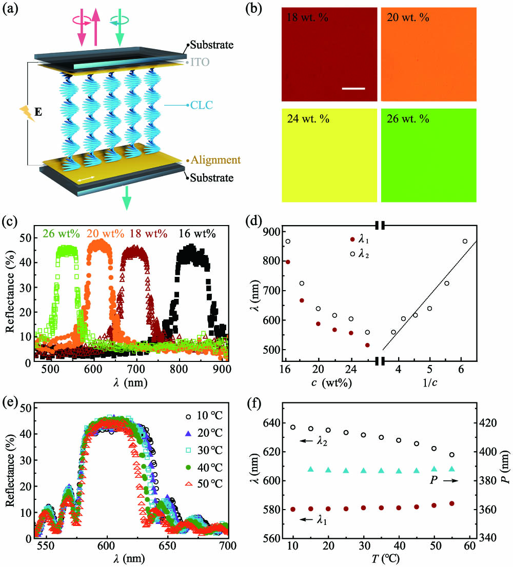
    Fig. 1. Optical characteristics of CLCs. (a) Schematic illustration of the 1D helical structure. Blue rods represent LC directors. White bidirectional arrow denotes the alignment direction. Green and pink arrows indicate the transmission and reflection of light. (b) POM images of planar CLCs at different c. They are taken under the reflection mode. Scale bar, 200 μm. (c) Reflection spectra of CLC mixtures with different c. The incident laser beam is linearly polarized. (d) Dependencies of λ1 and λ2 on c and 1/c. The dashed line is a linear fitting. (e) Reflection spectra of the CLC mixture at different temperatures. (f) λ1, λ2, and P as functions of the temperature at c=20.6%.
    Electro-optic responses of CLC. (a) Dynamics of the transmitted light intensity of CLC under E1≈62 V/μm, E2≈84 V/μm, E3≈107 V/μm, E4≈128 V/μm, and E5≈142 V/μm. (b) ΔI as a function of E. The dashed line shows the linear fitting. (c) Dependency of τmax on E.
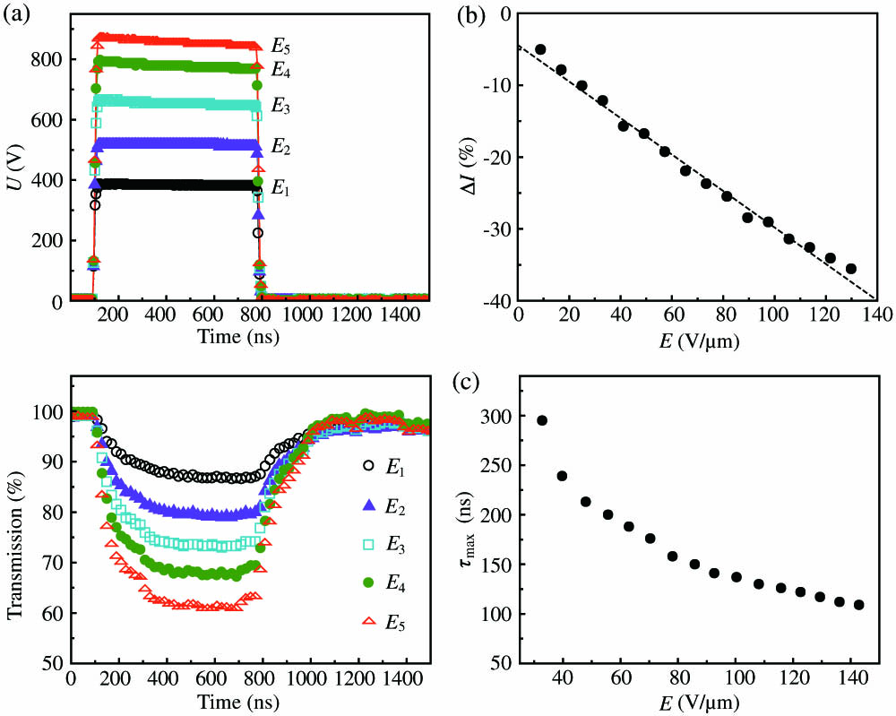
    Fig. 2. Electro-optic responses of CLC. (a) Dynamics of the transmitted light intensity of CLC under E162  V/μm, E284  V/μm, E3107  V/μm, E4128  V/μm, and E5142  V/μm. (b) ΔI as a function of E. The dashed line shows the linear fitting. (c) Dependency of τmax on E.
    Schematic illustration of field-induced effects. (a) Orientational order of LC molecules and ellipsoid optical tensor in the absence of an electric field. (b) Thermal fluctuation of the optical tensor. (c) Orientational order of LC molecules and elongated oblate optical tensor under an electric field. (d) Quenching of the optical tensor fluctuation.
    Fig. 3. Schematic illustration of field-induced effects. (a) Orientational order of LC molecules and ellipsoid optical tensor in the absence of an electric field. (b) Thermal fluctuation of the optical tensor. (c) Orientational order of LC molecules and elongated oblate optical tensor under an electric field. (d) Quenching of the optical tensor fluctuation.
    Three experimental geometries. (a) Geometry BU: n^ orients parallel to the plane of incidence. (b) Geometry UF: n^ is perpendicular to the plane of incidence. (c) Geometry FBU: the laser beam is normally incident to the cell. The polarization is 45º with respect to n^. Red bidirectional arrows indicate the incident polarizations. Black bidirectional arrows represent the alignment of LCs. In both BU and UF geometries, the incident angles are 45º, and the polarization of the incident light is 45º with respect to the plane of incidence.
    Fig. 4. Three experimental geometries. (a) Geometry BU: n^ orients parallel to the plane of incidence. (b) Geometry UF: n^ is perpendicular to the plane of incidence. (c) Geometry FBU: the laser beam is normally incident to the cell. The polarization is 45º with respect to n^. Red bidirectional arrows indicate the incident polarizations. Black bidirectional arrows represent the alignment of LCs. In both BU and UF geometries, the incident angles are 45º, and the polarization of the incident light is 45º with respect to the plane of incidence.
    Submicrosecond electro-optic switching of the nematic LC host. (a) Field-induced δn in three geometries. The duration of DC pulse is 400 ns; the amplitude is 142 V/μm. (b) Dynamics of δn at different E. (c) Dependency of δnmax on E. The dashed line is a parabola fitted curve. (d) Dependence of the τmax on the E. Data in (b)–(d) are obtained from experiments in geometry FBU.
    Fig. 5. Submicrosecond electro-optic switching of the nematic LC host. (a) Field-induced δn in three geometries. The duration of DC pulse is 400 ns; the amplitude is 142  V/μm. (b) Dynamics of δn at different E. (c) Dependency of δnmax on E. The dashed line is a parabola fitted curve. (d) Dependence of the τmax on the E. Data in (b)–(d) are obtained from experiments in geometry FBU.
    Lingling Ma, Chaoyi Li, Luyao Sun, Zhenpeng Song, Yanqing Lu, Bingxiang Li. Submicrosecond electro-optical switching of one-dimensional soft photonic crystals[J]. Photonics Research, 2022, 10(3): 786
    Download Citation