
Manoel P. Araújo, Stefano De Leo, Gabriel G. Maia, "Optimizing power oscillations in an ellipsometric system," Chin. Opt. Lett. 16, 031406 (2018)
- Chinese Optics Letters
- Vol. 16, Issue 3, 031406 (2018)
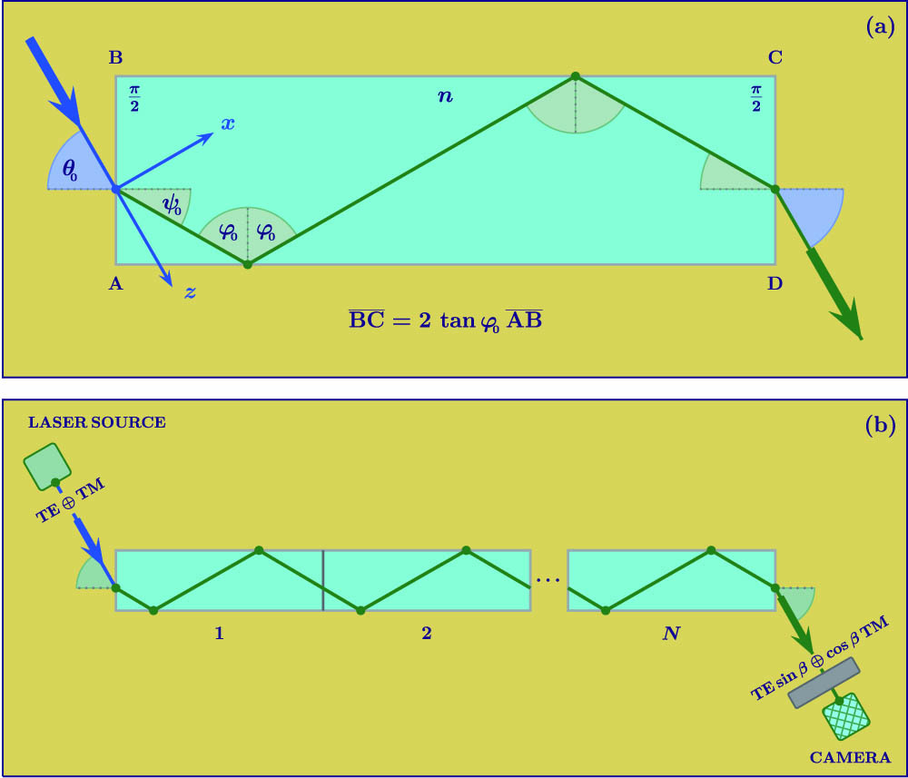
Fig. 1. (a) Building block of the proposed optical system. A beam composed of TE and TM polarized light enters the dielectric block through the left interface and is totally internally reflected. The ratio between its sides allows us to have two internal reflections for each block. (b) By lining together blocks like in (a), it is possible to have the geometry of the optical system as a controllable parameter. The experimental proposal is based on a polarizer-sample-analyzer ellipsometer.
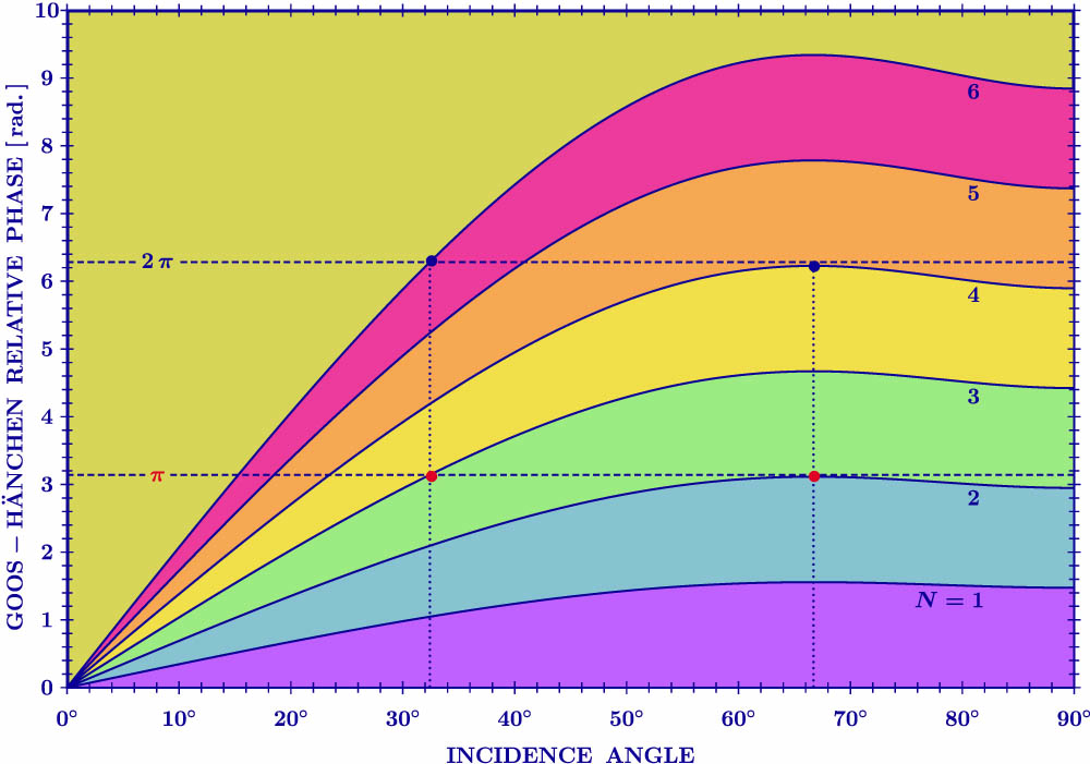
Fig. 2. Goos–Hänchen relative phase for different acrylic structures plotted as a function of the incidence angle. The curves for N = 3 N = 2 π
Fig. 3. Normalized power at the camera as a function of the longitudinal length of an acrylic structure. The dashed and continuous lines represent the power for the incidence angles 32.4° and 66.7°, respectively. The acrylic structure is done by using unitary acrylic blocks of 2.6 cm. An odd number of these blocks implies, for incidence at 32.4°, an odd number of internal reflections and, consequently, a transmitted beam forming and angle of − 32.4 °  ). For an even number of blocks and incidence at 32.4°, as well as for an even/odd number of blocks and incidence at 66.7°, the transmitted beam is parallel to the incident one, and the camera is positioned in the lower zone (
 ).
).
). For an even number of blocks and incidence at 32.4°, as well as for an even/odd number of blocks and incidence at 66.7°, the transmitted beam is parallel to the incident one, and the camera is positioned in the lower zone (). 

Set citation alerts for the article
Please enter your email address

© Copyright 2018-2021 | Chinese Laser Press. All Rights Reserved 沪ICP备15018463号-20