Manoel P. Araújo, Stefano De Leo, Gabriel G. Maia, "Optimizing power oscillations in an ellipsometric system," Chin. Opt. Lett. 16, 031406 (2018)
Copy Citation Text
Ellipsometry is a powerful and well-established optical technique used in the characterization of materials. It works by combining the components of elliptically polarized light in order to draw information about the optical system. We propose an ellipsometric experimental set-up to study polarization interference in the total internal reflection regime for Gaussian laser beams. The relative phase between orthogonal states can be measured as a power oscillation of the optical beam transmitted through a dielectric block, and the orthogonal components are then mixed by a polarizer. We show under which conditions the plane wave analysis is valid, and when the power oscillation can be optimized to reproduce a full pattern of oscillation and to simulate quarter- and half-wave plates.
In total internal reflection[1,2], the Fresnel reflection coefficient becomes complex and produces an additional phase in the electromagnetic field. In 1948[3], Artman showed that this phase is responsible for the lateral displacement of transverse electric (TE) mode, experimentally discovered one year before by Goos and Hänchen (GH)[4], by means of its derivative. In his derivation, based on the stationary phase method[5], Artmann, observing that the phase of the Fresnel coefficients is polarization-dependent, also predicted a different displacement for transverse magnetic (TM) waves, which was experimentally confirmed one year later by the same GH[6]. We will refer to this phase as the Fresnel phase, henceforth. As observed, it is polarization-dependent and so, if a linearly polarized beam composed of TE and TM polarizations is totally internally reflected, there is a relative phase between its components. Information about this relative phase is not, however, directly accessible through interference patterns analysis because they exist between orthogonal states, a problem with a solution in ellipsometry. Ellipsometry is an old and well-established characterization technique[7–10]. Interference patterns are the result of a phase difference between superposing waves[11], and, in most devices, this difference is induced by a set of beam splitters and mirrors that differentiate the optical paths of waves coming from the same source before recombining them[12]. In ellipsometers, however, the phase difference is provided by the polarization-sensitive response of the system, without the need for forced path differentiation, which justifies the qualification common path of this particular interferometer. The most remarkable difference, however, between ellipsometers and other interferometers is that, in the first, interference occurs between orthogonal polarization states[10].
This seems to be against one of the cornerstones of interferometry, that is states polarized in linearly independent directions do not interfere[12]. Notwithstanding this statement being true, it is possible to trigger interference using polarizers. Indeed, when light passes through a polarizer, the resulting amplitude is the weighted sum of the components of the previous field, and so, any relative phase between these components will have an effect in the final polarized field.
In this work, we present a detailed analysis of how the relative Fresnel phase of TM and TE phase changes when light undergoes multiple internal reflections within a chain of acrylic blocks. In particular, we study for which conditions the plane wave limit holds, when a full pattern of oscillation can be reproduced and in what circumstances the acrylic slab can simulate quarter- and half-wave plates.
Sign up for Chinese Optics Letters TOC. Get the latest issue of Chinese Optics Letters delivered right to you!Sign up now
The Jones matrix[1,2,11] for a polarizer set at an angle with respect to the axis is
If light, propagating along the axis and with an electric field where , passes through this device, the resultant electric field will be given by
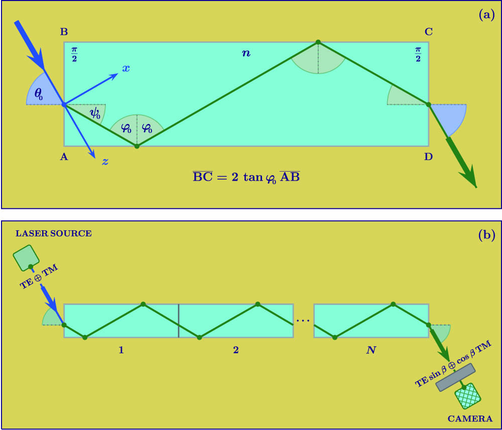
Our experimental proposal is based on the polarizer-sample-analyzer (PSA) ellipsometer, as depicted in Fig. 1.
Figure 1.(a) Building block of the proposed optical system. A beam composed of TE and TM polarized light enters the dielectric block through the left interface and is totally internally reflected. The ratio between its sides allows us to have two internal reflections for each block. (b) By lining together blocks like in (a), it is possible to have the geometry of the optical system as a controllable parameter. The experimental proposal is based on a polarizer-sample-analyzer ellipsometer.
Let us consider a linear polarized Gaussian laser, , with where is the minimal waist of the beam, is the beam’s wave number, is the wavelength, and . After passing through a polarizer set at an angle , the incident field hits the left side (air/dielectric interface) of the rectangular dielectric block as an equal mixture of TE and TM polarized light. The plane of incidence is the plane, and the incidence angle, taken with respect to the normal of the left interface, is , see Fig. 1. The refracted angle is given by the Snell law,
The reflection angle at the lower and upper (dielectric/air) interfaces, obtained from the geometry of the system, is
The transmitted field, forming an angle with the normal to the right (dielectric/air) interface, will have, with respect to the incident one, different TE and TM components:
A polarizer, set at an angle , will then combine the component amplitudes, before the beam is finally collected by a camera positioned at a distance from the origin of the axes located at the point of minimal waist of the Gaussian beam. The choice of the particular optical system depicted in Fig. 1 was made because a block with four right angles ensures, for , the total internal reflection regime for every possible incidence angle. Indeed, the Fresnel reflection coefficient becomes complex for , and this implies total internal reflection for incident angle satisfying
For experimental purposes, it is useful to have the geometry of the block as a controllable parameter. This is more easily achievable if we consider a structure composed of aligned blocks in such a way that becomes the parameter, and the structure’s length becomes a multiple of the unitary building block’s length, see Fig. 1(b). For this construction to work, we need the beam to undergo the same number of internal reflections in every block of the line. Being that and are the sides of the unitary dielectric block, from the laws of ray optics, it can be shown that the constraint fulfils this condition, allowing the beam to be reflected only twice per block. This double reflection per block requirement is convenient because it makes the incidence and transmission directions parallel, simplifying the geometry of the system.
When the beam interacts with the dielectric block, its angular distribution is modified by the Fresnel coefficients[13–15]. Since a paraxial beam is strongly collimated around the direction of propagation, the Fresnel coefficients can be calculated at the incidence angle, and the components of the transmitted field can be approximated to where ,
is the transmission amplitude of the block, which is obtained as the product of the transmission coefficients at the left and right interfaces, with , and . is the Snell phase, and is the Fresnel phase, obtained from the Fresnel coefficient of internal reflection,
The Snell phase in Eq. (10) is a global phase obtained by imposing the continuity at the air/dielectric and dielectric/air interfaces, and it is connected to the displacement in the same way that is connected to [5]. Essentially, the first-order derivative of the phase with respect to the incidence angle gives information about the beam’s trajectory. The displacement tells us where the transmitted beam will leave the dielectric and reproduces the path predicted by geometrical optics. is the correction to that prediction, the lateral GH shift[3,4,6]. Because , for the purposes of this letter, we can neglect it and write . This approximation allows us to work in the plane wave limit. Consequently, the results cannot depend either on the beam width or, directly, on the wavelength, only on the refractive index, incidence angle, and number of internal reflection. In the conclusion, we shall see when and how the power formula is affected by the GH lateral displacements and for which conditions and incidence angles the plane wave limit breaks down.
In the case in which the approximation holds, the power measured at the camera position, normalized by the incident power, is given by
After simple algebraic manipulations, we obtain the following expression: where and
It is interesting to give the reason that suggested the choice of acrylic as the material of our dielectric block. For (the acrylic refractive index is 1.491), , and .
So, observing that the first destructive interference is found when the condition is achieved, for incidence at after three unitary dielectric blocks with , and for incidence at after two unitary dielectric blocks with , we are in the vicinity of the destructive interference. Another advantage of using the refractive index and incidence angles and is that we can use the unitary block. This block guarantees two internal reflections for incidence at , but also guarantees a reflection for incidence at .
In Fig. 2, we plot the relative Fresnel phase for acrylic dielectric blocks () as a function of the incidence angle . For the incidence angle 32.4°, we find destructive and constructive interference for three and six unitary blocks, respectively. Observe that, for , the unitary acrylic block for this incidence angle is approximately 5.2 cm long. For incidence at 66.7°, the minimal and maximal oscillations are, respectively, found for two and four unitary acrylic blocks. In this case, the unitary block is . As observed above, an unitary acrylic block of 2.6 cm of length, if used for the incidence angle 32.4°, will give only one reflection for each block. The transmitted beam, coming out from an odd number of this unitary block, will be refracted by the right dielectric/air interface with a negative angle . Consequently, for the incidence angle 32.4° and an odd number of unitary acrylic blocks of 2.6 cm, the camera has to be positioned in the upper zone and not in the lower one, as in the case depicted in Fig. 1(b).
Figure 2.Goos–Hänchen relative phase for different acrylic structures plotted as a function of the incidence angle. The curves for and intercept the horizontal line at 32.4° and 66.7°, respectively. This configuration represents the configuration of maximal destructive interference.
The normalized transmitted power of Eq. (13) oscillates with an amplitude (maximized for a polarizer set at an angle ) given by around
As expected, we find for the results of for a polarizer, which selects the TE component (), and for a polarizer selecting the TM component (). For a polarizer that filters an equal mixture of TE and TM waves (), we find
For the incidence angles 32.4° and 66.7°, we have oscillations of amplitude of 0.92 around 0.46 and of 0.74 around 0.38, respectively, see Fig. 3. The choice of a polarization angle allows us to have the best destructive interference between the TE and TM beams, and, consequently, it represents the best experimental choice to see power oscillations. The choice of a unitary acrylic block of 2.6 cm allows us to build multiple block structures containing, for each block, two internal reflections for a beam incident at 66.7° and only a reflection for the incidence angle 32.4°. For an odd number of blocks and incidence at 32.4°, we have to position the camera in the upper zone, points indicated by in Fig. 3. In all of the other cases, an even number of blocks and incidence at 32.4° or an even/odd number of blocks and incidence at 66.7°, the camera is found in the lower zone, points indicated by in Fig. 3.
Figure 3.Normalized power at the camera as a function of the longitudinal length of an acrylic structure. The dashed and continuous lines represent the power for the incidence angles 32.4° and 66.7°, respectively. The acrylic structure is done by using unitary acrylic blocks of 2.6 cm. An odd number of these blocks implies, for incidence at 32.4°, an odd number of internal reflections and, consequently, a transmitted beam forming and angle of with the normal to the right interface, forcing us to move the camera to the upper zone (). For an even number of blocks and incidence at 32.4°, as well as for an even/odd number of blocks and incidence at 66.7°, the transmitted beam is parallel to the incident one, and the camera is positioned in the lower zone ().
The choice of an acrylic structure has the advantage of using the same unitary block of 2.6 cm length, which optimizes the interference for the two incidence angles. For example, if we had used BK7 () structures, we would have found for the incidence angles maximizing the interference for 32.4° and 60.2° and corresponding unitary blocks of 5.3 cm and 2.9 cm. The fact that these two blocks are not proportional to each other by an integer number does not allow us to use the block of minimal length for both incidence angles.
The interference studied in this letter does not depend on the particular shape of the optical beam. The optical system analyzed has the particularity of totally internally reflecting waves coming with any incidence angle from the outside, and so, light is never in the critical region, that is, the region around the critical angle. In the critical region, which is attainable for a inclined block or a right angle triangular prism, symmetry breaking effects occur because part of the beam is totally internally reflected, whereas part of it undergoes partial internal reflection[16–18]. In this case, the shape of the beam plays a role in the interference patterns. The study of the incidence region where beams reproduce the plane waves is interesting, however, as a limiting case and guide for limiting behavior of beams in the critical region and in view of possible experimental implementations. Another situation for which the shape of the optical beam and its width are important is when the GH lateral displacement, proportional to , cannot be discarded with respect to . This happens, for example, when the GH shift, amplified by multiple reflections (), is comparable with . In this case, the cosine term in the power oscillation formula in Eq. (13) has to be multiplied by the factor . The plane wave limit discussed in this letter is thus valid for a number of blocks .
In view of a possible experimental implementation, it is also important to observe that in Fig. 1 the acrylic blocks are placed adjacent to each other. Nevertheless, this is only a choice done to simplify our presentation. In the case of blocks separated by an air gap, the transmission coefficients become . Thus, the only change will be in the amplitude of oscillations.
Finally, we observe that the acrylic block presented in this letter can also be used to simulate quarter- and half-wave plates. For example, for the incidence angles analyzed in this letter, we can simulate a quarter-wave plate for incidence at 32.4° and an acrylic block of 7.8 cm and an half-wave plate for incidence at 66.7° and an acrylic block of 5.2 cm, see Fig. 3.
References
[1] M. Born, E. Wolf. Principles of Optics(1999).
[2] B. E. A. Saleh, M. C. Teich. Fundamentals of Photonics(2007).

 in Fig.
  ).
).