
Qinggang Lin, Xinming Yuan, Xuanke Zeng, Yatao Yang, Yi Cai, Xiaowei Lu, Maijie Zheng, Congying Wang, Wenhua Cao, Shixiang Xu, "Single-shot terahertz polarization detection based on terahertz time-domain spectroscopy," Photonics Res. 10, 1374 (2022)
- Photonics Research
- Vol. 10, Issue 6, 1374 (2022)
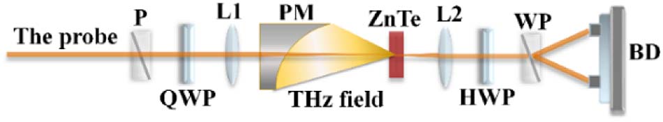
Fig. 1. Schematic diagram of 45° optical bias THz-TDS by EOS. P, polarizer; WP, Wollaston polarizer; QWP, quarter-wave plate; HWP, half-wave plate; L1, L2, lenses; PM, off-axis parabolic mirror; ZnTe, (110) ZnTe crystal; BD, balanced detector.
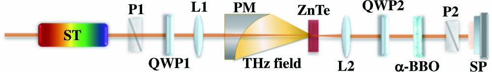
Fig. 2. Setup of SS-THz-PD. ST, pulse stretcher; P1, P2, polarizers; QWP1, QWP2, quarter-wave-plates; L1, L2, lenses; PM, off-axis parabolic mirror; ZnTe, (110) ZnTe crystal; α-BBO, α - BaB 2 O 4
Fig. 3. Illustration of the data process by simulation to extract the horizontal and vertical components of THz temporal waveforms.
Fig. 4. Comparison between the measured (blue lines) and the calculated (red lines) signals of the (a) horizontal and (b) vertical components from the THz temporal waveforms with circular polarization converted from the linearly polarized THz signal by using a 2.7 mm quartz plate.
Fig. 5. THz temporal signals measured by SS-THz-PD (red lines) and ICP-SI (blue lines) for three target polarizations: vertical linear polarization, − 60 °
Fig. 6. THz polarization distribution characteristics measured by SS-THz-PD (red line) and ICP-SI (blue line) for the target THz polarization states: (a) vertical polarization, (b) −60° polarization, and (c) right circular polarization.
Fig. 7. 300 groups of measured THz temporal signals by using SS-THz-PD (red color zones) and ICP-SI (blue color zones) and their RMS averages (black lines in the zones) for three target polarizations: vertical linear polarization, − 60 °
Fig. 8. 300 groups of measured THz temporal signals by using SS-THz-PD (red color zones) and traditional 45° optical bias THz-TDS by EOS (blue color zones) and their RMS averages (black lines in the zones): (a) horizontal components and (b) vertical components.


Set citation alerts for the article
Please enter your email address

© Copyright 2018-2021 | Chinese Laser Press. All Rights Reserved 沪ICP备15018463号-20