2Shanghai Jiao Tong University, State Key Laboratory of Advanced Optical Communication Systems and Networks, Department of Electronic Engineering, Shanghai, China
3University of L’Aquila, Department of Physical and Chemical Sciences, L’Aquila, Italy
Qi Wu, Zhaopeng Xu, Yixiao Zhu, Tonghui Ji, Honglin Ji, Yu Yang, Junpeng Liang, Chen Cheng, Gang Qiao, Zhixue He, Jinlong Wei, Qunbi Zhuge, Weisheng Hu, "Beyond 200-Gb/s O-band intensity modulation and direct detection optics with joint look-up-table-based predistortion and digital resolution enhancement for low-cost data center interconnects," Adv. Photon. Nexus 3, 036007 (2024)
Copy Citation Text
【AIGC One Sentence Reading】:We introduced a method combining LUT-based predistortion and digital resolution enhancement for high-speed, low-cost optical interconnects, achieving record data rates over short and long distances using low-resolution DACs, significantly improving signal quality.
【AIGC Short Abstract】:We introduced a method combining look-up-table-based predistortion and digital resolution enhancement to enable high-speed, low-cost optical connections using low-resolution digital converters. This approach mitigates pattern-dependent effects and shapes quantization noise, lowering DAC resolution requirements. We achieved record data rates for various PAM signals over short and long distances using this technique, demonstrating its effectiveness for affordable and efficient optical interconnects exceeding 200 Gb/s.
Note: This section is automatically generated by AI . The website and platform operators shall not be liable for any commercial or legal consequences arising from your use of AI generated content on this website. Please be aware of this.
Abstract
We propose a joint look-up-table (LUT)-based nonlinear predistortion and digital resolution enhancement scheme to achieve high-speed and low-cost optical interconnects using low-resolution digital-to-analog converters (DACs). The LUT-based predistortion is employed to mitigate the pattern-dependent effect (PDE) of a semiconductor optical amplifier (SOA), while the digital resolution enhancer (DRE) is utilized to shape the quantization noise, lowering the requirement for the resolution of DAC. We experimentally demonstrate O-band intensity modulation and direct detection (IM/DD) transmission of 124-GBd 4 / 6-level pulse-amplitude modulation ( PAM ) -4 / 6 and 112-GBd PAM-8 signals over a 2-km standard single-mode fiber (SSMF) with 3 / 3.5 / 4-bit DACs. In the case of 40-km SSMF transmission with an SOA-based preamplifier, 124-GBd on-off-keying (OOK)/PAM-3/PAM-4 signals are successfully transmitted with 1.5 / 2 / 3-bit DACs. To the best of our knowledge, we have achieved the highest net data rates of 235.3-Gb / s PAM-4, 289.7-Gb / s PAM-6, and 294.7 Gb / s PAM-8 signals over 2-km SSMF, as well as 117.6-Gb / s OOK, 173.8-Gb / s PAM-3, and -231.8 Gb / s PAM-4 signals over 40-km SSMF, employing low-resolution DACs. The experimental results reveal that the joint LUT-based predistortion and DRE effectively mitigate the PDE and improve the signal-to-quantization noise ratio by shaping the noise. The proposed scheme can provide a powerful solution for low-cost IM/DD optical interconnects beyond 200 Gb / s.
Intensity modulation and direct detection (IM-DD) systems have been widely deployed in cost-sensitive short-reach optical networks, including data center interconnects (DCIs) and metro applications1–10 because of their smaller footprint, simpler transceivers, and lower power consumption compared with coherent detection.11 As the next generation of Ethernet links aims for 800-GbE, or potentially even 1.6-TbE,12 there is an increased focus on enhancing single-wavelength data rates beyond .13–17 Nevertheless, achieving a single-lane data rate of remains a challenge for IM-DD optical interconnects, especially for DCI applications spanning distances of a few dozen kilometers,1,2,16 because the transmission distance of an IM-DD system in the C-band is limited by the chromatic dispersion-induced power fading.18
To achieve data rates exceeding for single lanes over distances greater than 40 km in DCI, the O-band is preferred for transmission because standard single-mode fiber (SSMF) exhibits lower group velocity dispersion at this wavelength.13,16 However, a critical challenge with O-band optical interconnects is transmission attenuation. In general, the semiconductor optical amplifier (SOA) is commonly used to mitigate the excess loss in the O-band due to its small size, simple structure, low cost, and ease of integration.19–23 However, the SOA also introduces the pattern-dependent effect (PDE) due to gain saturation. As the optical input power increases, the carriers in the SOA’s active region deplete and decrease the power gain.19 This nonlinear impairment can be mitigated through advanced digital signal processing (DSP) techniques, including Volterra nonlinear equalization, neural networks,20,21 and look-up-tables (LUTs).19 LUT-based predistortion significantly mitigates nonlinear impairment,24–26 but it also induces an increase in the peak-to-average-power ratio (PAPR). In addition to LUT-based predistortion, other preprocessing DSP techniques that combat intersymbol interference (ISI), such as pulse shaping with a small roll-off factor, Tomlinson–Harashima precoding (THP),27 pre-equalization used for the compensation for channel response,28,29 and chromatic dispersion precompensation (CDPC),30 also contribute to an increase in PAPR. The increase in PAPR reduces the signal-to-quantization noise ratio (SQNR) due to the limited resolution of the digital-to-analog converter (DAC),30 which hinders the use of high-order modulation formats for achieving higher transmission capacities. Therefore, to enhance SQNR, a high-resolution DAC is required, but this inevitably raises the cost of optical modules,31 which may not align with the cost-sensitive nature of short-reach optical networks.
Several shaping techniques have been proposed to facilitate the utilization of low-resolution and cost-effective DACs. Their primary objective is to squeeze quantization noise out of the signal band, leading to a notable enhancement in SQNR within the signal band. In Refs. [32] and [33], error feedback noise shaping (EFNS) is systematically studied in both IM-DD and coherent detection systems, enabling the use of a 3-bit DAC for a pulse-amplitude modulation (PAM)-4 signal. Furthermore, traditional quantization noise shaping (TQNS) and its enhanced variant, channel response-dependent noise shaping (CRD-NS), have been employed to reduce the demand for a high-resolution DAC.34–37 These techniques have been extensively evaluated for their effectiveness in mitigating quantization issues in discrete multitone (DMT) modulation with various quadrature amplitude modulation (QAM) orders.29,31 Most recently, the digital resolution enhancer (DRE) has been proposed in Ref. [38] and extensively investigated in the coherent detection,39–43 IM-DD system,34–45 Kramers–Kronig receiver,46 and free-space optics47,48 to dynamically mitigate quantization distortion. These reports have confirmed the powerful capability of DRE in reducing the required resolution of the DAC.
Sign up for Advanced Photonics Nexus TOC. Get the latest issue of Advanced Photonics Nexus delivered right to you!Sign up now
In this paper, we propose a joint LUT-based nonlinear predistortion and DRE-assisted noise-shaping scheme for beyond O-band IM-DD optics. We systematically investigate the transmission over both 2-km SSMF without a preamplifier and 40-km SSMF with an SOA-based preamplifier. The LUT with a memory size of three is employed to compensate for the PDE of the SOA for the transmission over 40-km SSMF, while the DRE allows for the use of low-resolution DACs. Our experimental results confirm that the proposed joint scheme effectively mitigates both nonlinear impairment and quantization-induced distortion. The remainder of this paper is structured as follows. Section 2 provides a detailed explanation of key DSP techniques, including the combination of LUT and DRE. Section 3 presents the experimental validation of the proposed DSP scheme and provides an analysis of the results. A comprehensive comparison is conducted between this paper and prior IM-DD reports based on low-bit DACs, considering important indicators such as baud rate, modulation format, achieved net data rate, transmission distance, and the required physical number of bits (PNoBs) of DAC. Finally, Sec. 4 provides a summary of this paper.
2 Principle
In this section, we introduce the essential DSP algorithms that will be utilized in the subsequent experiments: LUT and DRE. The LUT is employed to mitigate the PDE in the SOA, while the DRE is responsible for reducing quantization noise within the signal band, enabling high-speed transmission using a low-resolution DAC.
2.1 Look-Up-Table
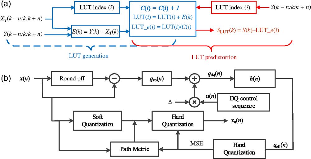
Figure 1(a) illustrates the generation procedures of LUT, comprising several essential steps.24–27 Initially, an empty LUT is initialized at the receiver’s end. Subsequently, a sufficiently long training sequence, denoted as , is transmitted. After optical transmission, the received signal is equalized. Before making decisions and demodulating the signal, we use a sliding window to select symbols from the recovered training sequence, referred to as , aligning with the transmitted symbols contained in . In this context, signifies the index within the training sequence. During this process, we calculate the difference between the known transmitted and recovered symbols, resulting in an error value at each window position, shown as
Figure 1.(a) Schematic of generation and predistortion procedures of LUT. , transmitted training symbols; , recovered training symbols; , the difference between the known transmitted symbols and the recovered symbols; , the counter; , averaged error; , transmitted payload symbols; , the predistorted symbols. (b) Schematic block diagram of DRE. , input signal needed to be converted to analog; , quantized version of ; , effective quantization error; , the round-off error; , an integer control sequence; DQ, dynamic quantization; Δ, DAC output step size; , the dynamic quantization error; , the combined frequency response of the channel and the matched filtering.
The selected sequence of symbols from the transmitted side serves as the basis for determining the LUT address, referred to as the LUT index (). Meanwhile, a counter denoted by is incremented to track the number of updates for that particular sequence. For each within the training symbols, the amplitude differences are accumulated in the respective LUT entry corresponding to different patterns, which are denoted as
After the training procedure, LUT entries are normalized by dividing each by its respective update count, resulting in averaged error corrections which can be expressed as
In the application of LUT-based predistortion at the transmitter side after training, another sliding window is employed to traverse the transmitted symbol sequence, . Consequently, the middle symbols among the selected symbols are adjusted utilizing the error generated during the training phase, denoted as
This predistorted symbol accounts for the PDE in the SOA-based communication channel. In this paper, we set to 1 to ensure low computational complexity and a smaller LUT memory size. Here, we take the PAM-4 modulation in our experiments as an example. Figure 2 displays the periodic pattern errors versus the pattern index. The amplitude differences range from to 0.3, which is noticeable for PAM-4 symbol levels (). Therefore, a LUT with a length of three can effectively mitigate the SOA-induced pattern-dependent nonlinear impairment.
Figure 2.Pattern error versus pattern index for PAM-4 signal in the following experiment.
Figure 1(b) illustrates the principle of DRE for shaping the noise spectrum through dynamic quantization control. This control inversely corresponds to the combined time-domain pulse response of the channel and the matched filtering at the receiver, denoted by . In this paper, the channel response is acquired using a receiver-side equalizer, while both transmitter and receiver are equipped with a known matched filter. The frequency response of , illustrated in Fig. 3(a), exhibits a predominantly low-pass characteristic due to the inherent bandwidth limitations of the transceiver. As a result, quantization noise within the signal band experiences a reduction, leading to a considerable improvement in SQNR. While DRE may lead to an increase in quantization noise at high frequencies, the low-pass characteristics of the channel and the matched filter at the receiver help mitigate the heightened quantization noise outside the signal band. This results in an overall increase in the SQNR of the system.
Figure 3.(a) Combined response of the channel and the matched filtering. (b) Electrical spectra of quantized signals for 124-GBd PAM-4 modulation with and without DRE.
To reduce quantization noise, the first step involves defining a metric for quantization noise. The quantization noise for each digital sample is expressed as where represents the quantized version of the digital input signal that needs to be converted to analog. The signal transmitted over the channel, after passing through the matched filter, is denoted as . The effective quantization error, denoted as , is then calculated as , where signifies the received signal in the absence of quantization noise. It is this effective quantization error that DRE aims to minimize, as it represents the perceived quantization noise at the receiver. In the case of a linear channel, the effective quantization noise can be computed as where * denotes convolution. From Eq. (6), it is evident that should be selected in a manner that minimizes the result when is convolved with .
The quantization noise is shaped by avoiding the conventional method of selecting the DAC output with the smallest Euclidean distance to the input sample, i.e., rounding off. Instead, it is achieved by dynamically quantizing the DAC output, as shown in Fig. 1(b). An input sample is quantized into one of three soft quantization possibilities, representing the three closest DAC outputs to the input sample. This is mathematically expressed as where represents the error if a standard round-off quantizer is used, is an integer control sequence that is composed of , 1, and 0, influencing the chosen DAC output, and is the DAC output step size.
The optimal DAC outputs and consequently are determined by minimizing the mean squared error (MSE) as defined below, where is the number of samples in the input signal. However, the computational complexity would be unacceptable due to the exponential growth in the number of quantization combinations with . Taking a 3-bit quantizer (i.e., eight levels) as an instance, there would be different quantization combinations. It is infeasible to find the optimal by exhaustively evaluating Eq. (8) for all combinations. Instead, the optimal is determined using the block-wise Viterbi algorithm. In a nutshell, the DRE process involves several quantization procedures. The first step, known as soft quantization, focuses on quantizing each digital sample, , into three possible values. Next, we calculate the quantization error for each of the three soft quantization possibilities. When observing a sequence of digital samples, we compute a path metric error for each potential sequence. Finally, these path metric errors are sent to the hard quantization block, thereby determining the best quantized values for the given data sequence.
With the aid of dynamic quantization control, quantization noise is pushed outside the signal band, resulting in an enhancement of the SQNR within the signal band. To provide an intuitive illustration of quantization noise using uniform quantization and DRE quantization, we have plotted the electrical spectrum of the transmitted 124-GBd PAM-4 signal with and without DRE using a 3-bit DAC in Fig. 3(b). The plots reveal that quantization noise is mostly concentrated at frequencies beyond 62 GHz with the help of DRE.
3 Experimental Results and Discussion
In this section, we introduce the experimental setup and DSP procedures used in this experiment, as displayed in Figs. 4(a) and 4(b), respectively. At the transmitter-side DSP, random bits in MATLAB are mapped into PAM symbols with a length of 131,072. For the 2-km SSMF transmission, the PAM symbols are upsampled to two samples-per-symbol (SPS) and shaped by a root-raised cosine (RRC) filter with a roll-off factor of 0.1. In the case of 40-km transmission, LUT-based predistortion is applied before the upsampling and pulse-shaping process due to the SOA-induced pattern-dependent impairment. The LUT is generated using a sufficiently long training sequence in advance. Subsequently, the digital samples are resampled to to match the sampling rate of the arbitrary waveform generator (AWG, Keysight 8199B). Before loading the samples into the AWG, the DRE is employed to reduce quantization noise within the signal band, as introduced earlier. The AWG converts the digital samples to analog electrical signals with a peak-to-peak voltage of 2.7 V. These electrical signals drive the Mach–Zehnder modulator (MZM, 50 GHz), biased at the quadrature point, to modulate the light from an O-band distributed feedback laser, operating at 1310.116 nm with an optical output power of . The optical signal, with a power of around , is injected into the SSMF; its spectrum is depicted in Fig. 4(c).
Figure 4.(a) Experimental setup. DFB, distributed feedback; AWG, arbitrary waveform generator; MZM, Mach–Zehnder modulator; SSMF, standard single-mode fiber; SOA, semiconductor optical amplifier; VOA, variable optical attenuator; PD, photodiode; RTO, real-time oscilloscope. (b) DSP procedures implemented at the transmitter and receiver sides. RRC, root-raised cosine; LUT, look-up-table; DRE, digital resolution enhancer. (c) Optical spectrum of 124-GBd PAM-4 signal. (d) Received electrical spectrum of 124-GBd PAM-4 signal.
At the receiver side, for the 2-km transmission, the optical signal is captured by a single photodiode (Keysight, N4377A), while an SOA (inphenixIPSAD1301) serves as a preamplifier to mitigate the attenuation at the O-band in the case of 40-km transmission. Here, a variable optical attenuator (VOA) is used to adjust the received optical power (ROP) for testing the system’s performance. The detected electrical signals are digitized using a real-time oscilloscope (RTO, Keysight UXR0594AP) with a brick-wall bandwidth of 62 GHz. The receiver’s electrical spectrum of the 124-GBd PAM-4 signal is plotted in Fig. 4(d), and it shows that quantization noise outside 62 GHz is removed by the bandwidth limitations of the transceiver. In the receiver DSP, the digitized samples are resampled to 2 SPS, and then, matched filtering is applied. Synchronization is performed based on 1024 training symbols inserted at the beginning of the frame, and a linear equalization with 101 taps is employed to eliminate ISI. The equalizer weights are updated based on the training symbols using the recursive least square algorithm. Subsequently, the equalized samples are down-sampled to 1 SPS and de-mapped into PAM symbols. Finally, the bit error rate (BER) is calculated by averaging the results of five measurements.
3.1 2-km SSMF Transmission Without SOA
We investigate the system performance for the 2-km SSMF transmission. Figure 5(a) shows BERs as a function of PNoB. It is evident that the BER performance significantly improves with an increase in PNoB, as a high-resolution DAC provides more levels for signal quantization. Under a 1-bit DAC, the BER improvement with DRE is not considerable, since the overall SQNR remains notably low. In Fig. 5(b), we plot measured BERs as a function of ROP for the 124-GBd PAM-4 signal. The results indicate that DRE allows relaxation of 1 bit in the required PNoB compared with the signal without DRE under the BER threshold of KP4-feed-forward error correction (KP4-FEC). With a 3-bit DAC and DRE, the measured BER under an ROP of reaches , meeting the BER threshold of KP4-FEC at . In addition, with the same PNoB of four, the receiver with DRE exhibits higher ROP sensitivity compared with the one without DRE at KP4-FEC. The overhead of KP4-FEC is 5.4%, and thus, the net bit rate is calculated as .
Figure 5.Measured BERs versus ROP in the case of 2-km SSMF transmission for (a) 124-GBd PAM-4, (e) 124-GBd PAM-6, and (i) 112-GBd PAM-8 signals. Measured BERs versus PNoB in the case of 2-km SSMF transmission for (b) 124-GBd PAM-4, (f) 124-GBd PAM-6, and (j) 112-GBd PAM-8 signals. Electrical spectra with and without DRE of (c) 124-GBd PAM-4 signal using a 3-bit DAC, (g) 124-GBd PAM-6 signal using a 3.5-bit DRE, and (k) 112-GBd PAM-8 signal using a 4-bit DRE. Temporary amplitudes versus sample index of (d) 124-GBd PAM-4 signal with a 3-bit DAC and DRE, (h) 124-GBd PAM-6 signal with a 3.5-bit DAC and DRE, and (l) 112-GBd PAM-8 signal with a 4-bit DAC and DRE.
The results also prove that the signal with DRE is more tolerant to a low-resolution DAC, since the quantization noise is pushed outside the signal band, which is shown in Fig. 5(c). It can be observed that the quantization noise concentrates on frequencies beyond 62 GHz, and thus, the power of quantization noise below 62 GHz is lower than that of uniform quantization (i.e., without DRE). The amplitudes of the output of DRE are shown in Fig. 5(d). Eight levels are shown because of the use of a 3-bit DAC.
Subsequently, we transition to PAM-6 modulation while maintaining the same baud rate. The measured BERs as a function of PNoB are provided in Fig. 5(e). When the PNoB of DAC is beyond six, the BER improvement from DRE becomes negligible, as electrical noise in the receiver becomes the dominant noise source. However, DRE still reduces the required DAC resolution by 1 bit. Figure 5(f) depicts the measured BERs as a function of ROP with and without DRE using DACs. It shows that the DRE successfully achieves the BER below the threshold of of 7% hard-decision forward error correction (HD-FEC) using a 3.5-bit DAC, meaning that 12 quantization levels can transmit a 124-GBd PAM-6 signal over 2-km SSMF. Thus, the net bit rate of PAM-6 modulation is calculated as . Under a PNoB of 3.5, we also plot the electrical spectra with and without DRE in Fig. 5(g), and the amplitudes of analog levels are displayed in Fig. 5(h). Compared with PAM-4, PAM-6 requires four additional levels due to its higher requirement for SQNR.
To explore the system’s maximum achievable data rate, we decrease the baud rate from 124 to 112 GBd and switch to PAM-8 modulation. Although the baud rate is decreased, the BER performance deteriorates due to the selection of a higher modulation format, making the system more sensitive to ISI. In Fig. 5(i), we plot the measured BERs versus PNoB. The BER threshold of 7% HD-FEC is no longer reached even with the reduced baud rate. Consequently, we adopt the BER threshold of 14% HD-FEC49 at for PAM-8 modulation. Figure 5(j) shows the BERs as a function of ROP with and without the DRE. The inclusion of a 4-bit DAC and DRE allows the system to transmit a 112-GBd PAM-8 signal with a BER below . Furthermore, in Fig. 5(k), we illustrate the electrical spectra with and without DRE using a 4-bit DAC. Compared with Fig. 5(c), it is apparent that the difference in noise power between DRE quantization and uniform quantization diminishes due to the increased DRE quantization level. We also provide samples of the transmitted PAM-8 signal with 16 levels in Fig. 5(l). The result shows that with the increase of modulation order, the requirement for higher SQNR will be strengthened. The net bit rate of PAM-8 modulation is calculated as .
3.2 40-km SSMF Transmission with SOA
In this subsection, we set the fiber length to 40 km to meet the requirements of DCI. Simultaneously, an SOA is introduced to mitigate excess attenuation in the O-band. The SOA operates at a temperature of 31°C with a bias current of 340 mA. The power gain of the SOA is adjusted to to compensate for the transmission loss over 40-km SSMF, thereby potentially supporting longer transmission distances. However, for shorter transmission reaches, it is anticipated that the power gain will be reduced to mitigate PDE. We investigate three modulation formats: on-off-keying (OOK), PAM-3, and PAM-4. The PDE imposes nonlinear impairment on this system, limiting its support for high baud rates and high-order modulation formats simultaneously. When SOA is applied in the system, LUT predistortion is used to effectively address the induced PDE impact. In Fig. 6(a), we display the measured BERs as a function of PNoB for a 124-GBd OOK signal with and without DRE under an ROP of . It shows that the utilization of LUT effectively mitigates the nonlinear impairment induced by SOA. In addition, the BER improves considerably with the increase of PNoB, and a BER below can be achieved using a 3-bit DAC and DRE. Figure 6(b) plots the BERs as a function of ROP with and without DRE using DACs. With the increase in ROP, there is a BER floor as the dominant impairment gradually transitions from the electrical noise of the photodiode to the quantization noise. Thus, enhancing the ROP does not yield a substantial BER improvement. It is illustrated that the system’s performance with a 1.5-bit DAC and DRE can reach the BER threshold required for KP4-FEC. The net bit rate of OOK modulation over 40-km SSMF is calculated as . In Fig. 6(c), we provide the transmitted signal spectra with and without DRE when using a 1.5-bit DAC. It demonstrates that DRE significantly alleviates the quantization noise at frequencies below 62 GHz. In addition, the amplitudes versus samples are given in Fig. 6(d). OOK modulation achieves the KP4-FEC BER threshold with just three levels.
Figure 6.Measured BERs versus PNoB in the 40-km SSMF transmission for (a) 124-GBd OOK, (e) 124-GBd PAM-3, and (i) 124-GBd PAM-4 signals. Measured BERs versus ROP in the 40-km SSMF transmission for (b) 124-GBd OOK, (f) 124-GBd PAM-3, and (j) 124-GBd PAM-4 signals. Electrical spectra with and without DRE of (c) 124-GBd OOK with a 1.5-bit DAC, (g) 124-GBd PAM-3 with a 2-bit DAC, and (k) 124-GBd PAM-4 with a 3-bit DAC signals. Temporal amplitudes versus (d) 124-GBd OOK signal with a 1.5-bit DAC and DRE, (h) 124-GBd PAM-3 signal with a 2-bit DAC and DRE, and sample index (l) 124-GBd PAM-4 signal with a 3-bit DAC and DRE.
Subsequently, we improved the modulation format to PAM-3. The measured BERs versus PNoB are displayed in Fig. 6(e). Compared with OOK modulation, PAM-3 requires one more quantization level to support high-order modulation, and a BER below can be achieved with a 5-bit DAC and DRE. Figure 6(f) depicts the BER as a function of ROP over 40-km transmission. The DRE with a 2-bit DAC enables this system to achieve a BER below the 7% HD-FEC threshold. The net bit rate is , calculated as . The transmitted spectra are displayed in Fig. 6(g), and the corresponding amplitudes are shown in Fig. 6(h). Compared with OOK modulation, PAM-3 requires one additional level to suppress quantization noise.
Finally, to achieve an optical interconnect beyond 200 Gbps, we employ PAM-4 modulation with a baud rate of 124 GBd. The BER results versus PNoB at an ROP of 4 dBm are shown in Fig. 6(i). The best BER with an 8-bit quantization is . Figure 6(j) shows the BERs as a function of ROP. The threshold of 7% HD-FEC can be reached using a 3-bit DAC and DRE with a net data rate of , calculated as . The transmitted spectra of the predistorted PAM-4 signal are shown in Fig. 6(h), and the amplitudes versus samples with DRE are displayed in Fig. 6(l). Achieving a 7% HD-FEC with PAM-4 modulation requires a 3-bit DAC and eight levels.
3.3 Discussion
Table 1 provides a comprehensive comparison of high-speed IM-DD transmission systems using low-resolution DACs. The key concepts revolve around shaping quantization noise through techniques such as EFNS, TQNS, CRD-NS, or DRE. Leveraging higher-order modulation formats imposes more stringent requirements on the PNoBs of the DAC and the SQNR. For instance, conventional PAM-4 modulation28,37 requires three or four PNoBs to meet the BER threshold of FEC. In addition, DMT modulation, which employs the discrete Fourier transformation, leads to higher PAPR and thus necessitates a higher number of PNoBs to mitigate the impact of quantization noise29,36. Specifically, it is shown that PNoBs are required for -QAM-DMT modulation, as demonstrated in Ref. [31]. In Ref. [30], a joint DSP scheme involving CDPC, clipping, and DRE is presented to achieve an 80-km transmission. CDPC compensates for chromatic dispersion (CD) in the transmitter-side DSP, eliminating the influence of CD, while clipping is employed to reduce the PAPR of the pre-compensated signal.
Reference
Baud rate (GBd)
Modulation format
Net data rate (Gb/s)
Band
Distance (km)
Resolution of DAC (bit)
DSP method
FEC
Ref. 28
28
PAM-4
52.3
C
80
4
EDC, TQNS
7% HD-FEC
Ref. 32
32
PAM-4
59.8
C
10
3
Preequalization, EFNS
7% HD-FEC
Ref. 33
40
PS-PAM-4
74.1
C
3
3
Preequalization, EFNS
7% HD-FEC
Ref. 31
50
16/32/64-QAM-DMT
91.7/114/137.5
C
2
4/5/6
Preequalization, TQNS
7% HD-FEC
Ref. 45
50
PAM-4
93.5
N/A
0
3
Preequalization, DRE
BER = , <7% HD-FEC
Ref. 36
50
DFT-S-32-QAM-DMT
93.5
C
2
5
Preequalization, TQNS
7% HD-FEC
Ref. 29
50
DMT
93.5
C
2
3
Preequalization, CRD-NS
7% HD-FEC
Ref. 37
55
PAM-4
102.8
C
2
3
Preequalization, CRD-NS
7% HD-FEC
Ref. 44
56
PAM-4
104.7
C
40
4
THP, DRE
7% HD-FEC
Ref. 30
56
PAM-4
104.7
C
80
3
CDPC, Clipping, DRE
7% HD-FEC
Ref. 35
60
PAM-4
112.1
O
40
4
Preequalization, TQNS
7% HD-FEC
This work
124
PAM-4
235.3
O
2
3
DRE
KP4-FEC
This work
124
PAM-6
289.7
O
2
3.5
DRE
7% HD-FEC
This work
112
PAM-8
294.7
O
2
4
DRE
14% HD-FEC
This work
124
PAM-2
117.6
O
40
1.5
LUT predistortion, DRE
KP4-FEC
This work
124
PAM-3
173.8
O
40
2
LUT predistortion, DRE
7% HD-FEC
This work
124
PAM-4
231.8
O
40
3
LUT predistortion, DRE
7% HD-FEC
Table 1. Comparison of high-speed IM-DD optics with low-resolution DAC.
In this work, we systematically investigated various single-carrier modulation formats, ranging from OOK to PAM-8, over both 2-km and 40-km O-band SSMF transmission links under low-bit DAC scenarios. For the 2-km transmission, we find that using a DAC with PNoBs allows us to meet the BER thresholds of KP4-FEC, 7% HD-FEC, and 7% HD-FEC for modulation formats, respectively, aided by effective DRE. However, in the case of 40-km transmission, the achieved data rate is significantly reduced due to the PDE of the employed SOA. Consequently, we propose joint LUT-based predistortion and DRE and opt for lower-order OOK/PAM-3/PAM-4 signals, which require PNoBs, respectively. The experimental results we present demonstrate that the proposed approach effectively relaxes the requirements for the resolution of the DACs beyond IM-DD optics. To the best of our knowledge, we experimentally demonstrate the highest net data rates of for PAM-4, for PAM-6, and for PAM-8 signals over a 2-km SSMF using DACs, respectively. In the case of a 40-km SSMF transmission, we also achieve record net data rates of for OOK, for PAM-3, and for PAM-4 signals over a SSMF using DACs, respectively.
The DRE demonstrates excellent performance in suppressing quantization noise, albeit at the expense of high computational complexity.29,32 In addition, the oversampling ratio before the data are loaded into a DAC significantly impacts both performance and system cost. A higher oversampling ratio allows for a broader frequency band to accommodate quantization noise. In our experiment, we employ an oversampling ratio of less than 2, prioritizing high-speed transmission through a high baud rate. Therefore, practical implementation requires a delicate balance of optimizing performance, managing computational complexity, and considering system cost. Furthermore, amplitude clipping offers another avenue for mitigating quantization noise. Investigating the potential synergies between clipping and DRE could further enhance the performance of our system. This will be a key focus of our future research.
4 Conclusion
In this paper, we propose a joint LUT-based predistortion and DRE-aided quantization-shaping scheme to enable optical interconnects beyond in the O-band IM-DD system, using low-cost SOA and low-resolution DACs for short-reach optical networks. The LUT is employed to mitigate the PDE of the SOA, while DRE suppresses quantization noise within the signal band, thereby improving the SQNR. We experimentally demonstrate the transmission of 124-GBd and 112-GBd PAM-8 signals over 2-km SSMF with DACs. In addition, for 40-km transmission, we achieve 124-GBd transmission using DACs. The highest data rates achieved for 2-km and 40-km transmissions are and , respectively, meeting the requirements for next-generation high-speed Ethernet optical links targeting at . To the best of our knowledge, these are the highest net data rates reported using low-bit DAC. Our experimental results confirm the effectiveness of our proposed scheme for O-band IM-DD systems with high baud rates. We believe it will provide a powerful solution for cost-sensitive optical interconnects, including DCI and 6G fronthaul access networks.
[8] Q. Wu et al. 405-GBd OOK and 201-GBd PAM-4 IM/DD optics at record faster-than-Nyquist ratios of 226.6% and 62.1% enabled by advanced noise whitening, ACPPOEM-1007-5(2023).
Qi Wu, Zhaopeng Xu, Yixiao Zhu, Tonghui Ji, Honglin Ji, Yu Yang, Junpeng Liang, Chen Cheng, Gang Qiao, Zhixue He, Jinlong Wei, Qunbi Zhuge, Weisheng Hu, "Beyond 200-Gb/s O-band intensity modulation and direct detection optics with joint look-up-table-based predistortion and digital resolution enhancement for low-cost data center interconnects," Adv. Photon. Nexus 3, 036007 (2024)
 AI Video Guide
  AI Picture Guide
 AI One Sentence