
Jinkui Chu, Hanpei Hu, Zhenhua Wan, Jinshan Li. Visual Inertial Navigation System Aided by Polarized Light[J]. Laser & Optoelectronics Progress, 2023, 60(7): 0726002
- Laser & Optoelectronics Progress
- Vol. 60, Issue 7, 0726002 (2023)
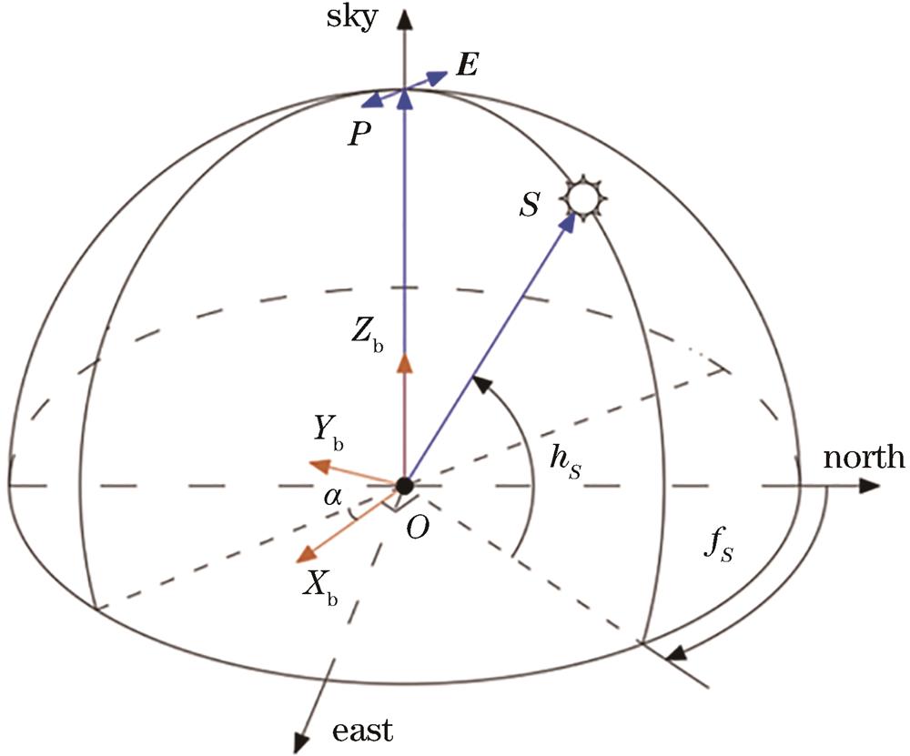
Fig. 1. Principle of polarized light orientation
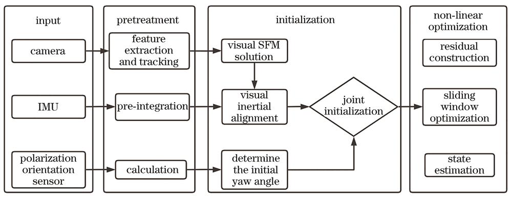
Fig. 2. Block diagram of integrated navigation system assisted by polarized light
Fig. 3. Integrated navigation system experimental platform
Fig. 4. Vehicle-mounted navigation diagram
Fig. 5. Navigation trajectory comparison (experiment 1)
Fig. 6. RPE of integrated navigation system (experiment 1)
Fig. 7. RPE of original navigation system (experiment 1)
Fig. 8. Navigation trajectory comparison (experiment 2)
Fig. 9. Navigation course angle comparison (experiment 2)
Fig. 10. RPE of integrated navigation system (experiment 2)
Fig. 11. RPE of original navigation system (experiment 2)
|
Table 1. Information of integrated navigation system sensor
|
Table 2. Navigation mode error comparison (experiment 1)
|
Table 3. Navigation mode error comparison (experiment 2)

Set citation alerts for the article
Please enter your email address
© Copyright 2018-2021 | Chinese Laser Press. All Rights Reserved 沪ICP备15018463号-20