
Xuan He, Bin Zhang, Shuailin Liu, Linyong Yang, Jinmei Yao, Qilin Wu, Yuxin Zhao, Tao Xun, Jing Hou, "High-power linear-polarization burst-mode all-fibre laser and generation of frequency-adjustable microwave signal," High Power Laser Sci. Eng. 9, 02000e13 (2021)
- High Power Laser Science and Engineering
- Vol. 9, Issue 2, 02000e13 (2021)
Abstract
1. Introduction
Recently, microwave photonics has attracted increased attention as a novel research field bridging the microwave and optics fields[1,2]. A variety of works have been reported on generating desirable and agile radiofrequency (RF) or microwave signals, e.g., spectral shaping and frequency-to-time mapping[3,4], space-to-time optical pulse shaping[5] and multi-wavelength carried RF frequency signals [6]. In addition, a solid-state microwave signal could be generated by a linearly responded photoconductive semiconductor switch (PCSS) when it is illuminated by a pulsed laser. Compared with the traditional microwave generation, typically based on vacuum electron devices, one prominent advantage of the solid-state microwave signal generation is the smart frequency agility as well as the bandwidth tuneability in the frequency domain. In addition, solid-state microwave signal generation has a two to three orders of magnitude larger power-to-volume ratio, feasibility of array combining and so on[7,8]. In fact, generation of a solid-state microwave signal with ~10 MW peak power and nanosecond pulse duration has been reported[8,9]. The generated high-peak-power microwave signal could directly inherit the temporal profiles of the incident pulse laser such as waveform and frequency, i.e., a temporally modifiable pulsed laser could generate high-power agile microwaves. This microwave generation scheme is more attractive in pulsed-power sources which are designed to deliver a specified amount of energy in a very short time and results in a high peak power for the duration of the pulse[10]. Thus, a bunch of tuneable pulse laser is desired, which is known as a burst-mode pulse laser. Based on the Fourier transform theory, intuitively, the intra-burst temporal parameters are quite important. For instance, the tuneable intra-burst repetition rate determines the generated radiation microwave frequency and the near-sine intra-burst shape could influence its signal-to-noise ratio and harmonic generation. However, there are few reports of solid-state microwave signal generation by burst-mode lasers, which are applicable to many areas such as smart adaptive radar or intelligent microwave systems.
Burst-mode lasers possess temporal speciality, i.e., the desired bunch of high-repetition-rate intra-burst pulses, which have been widely applied in material processing, simultaneous measurement of multiple physical fields, microstructure machining, space debris laser ranging, etc.[11-14] All-fiberized burst-mode lasers have the practical advantages of being highly compact, robust, maintenance-free and the high-power technology is mature[15]. Chen et al.[16] realized a burst-mode seed laser directly utilizing a high-speed driving circuit. The highest intra-burst repetition rate is limited to 333 MHz and the intra-burst waveforms could not be programmed. In addition, a dispersion-management mode-locked laser with a fixed high repetition rate and a time gate by an acousto-optic modulator (AOM) could also generate burst-mode laser pulses[17]. However, the intra-burst repetition rate could not be tuned flexibly because it is determined by the mode-locked laser. An actively mode-locked and gain-switched laser diode (LD) can make tuneable high repetition possible, but the other intra-burst parameters cannot be tuned, such as shape and duty circle[18,19]. Furthermore, a continuous laser modulated by two electrical optic modulators (EOMs) could realize an all-temporal-parameter adjustable burst-mode seed with high stability and high technological maturity[20]. However, this scheme would induce prodigious power loss when the duty of the burst is low, such as kilohertz repetition rate and nanosecond burst duration. In particular, in this paper, we adopt a combination of EOM and AOM to modulate the pulsed laser for generating a burst-mode seed with flexible tuneability, including the intra-burst frequency, duty, intra-burst waveforms, filtering the amplified spontaneous emission (ASE) noise in the time domain and altering the burst seed envelope, which could satisfy the requirement of adaptive microwaves. The pulse energy and peak power of the burst-mode seed laser could be promoted by a master oscillator power amplifier (MOPA) configuration, whereas the gain saturation effect would induce the distortion of the burst envelope. In general, to realize the homogenous energy distribution in each burst, i.e., decrease the envelope distortion of the amplified burst pulse, a pre-compensation technique is necessary in the MOPA configuration.
In this paper, we report an all-fibre temporally tuneable linearly polarized burst-mode laser and generation of high-power microwave signals with gigahertz-level frequency. A pre-compensation technique is adopted to realize the rectangular burst envelope shape. The maximum burst energy is 200 μJ with 100 ns burst duration, with an average power and a peak power of 10 W and 4 kW, respectively. In addition, illuminating on the linearly responded PCSS, up to 300 W peak power, 0.80–1.12 GHz adjustable narrowband microwave signal is firstly realized, to the best of the authors’ knowledge.
Sign up for High Power Laser Science and Engineering TOC. Get the latest issue of High Power Laser Science and Engineering delivered right to you!Sign up now
2. Experimental setup
The experimental setup of linear-polarization burst-mode all-fibre laser is illustrated in Figure 1. The repetition and duration of the electrical pulse-driven narrow-band FBG laser LD1 (externally triggered by PWM1 as shown in Figure 1) are set as 50 kHz and 100 ns, respectively. The average output power and 3 dB spectral linewidth of the pulse laser are 4.6 mW and 0.09 nm, respectively. One bi-directional-pumped amplifier (shown as Pre-amp) is constructed by a polarization-maintaining (PM) Yb3+-doped single-cladding active fibre with core/cladding diameter of 6/125 μm, two pump LDs centred at 974 nm and wavelength division multiplexers (WDMs), which promotes the average power from 4.6 mW to 120 mW. An AOM driven by an analogue–digital dual-channel driver (bandwidth 200 MHz, insertion loss 2.3 dB) is triggered synchronously to change the pulse temporal shape (triggered by PWM2) and turn off the inter-burst ASE noise (triggered by PWM3 and the gate time decided by the high-level duration of PWM3). Then the seed pulse is modulated as a gigahertz sinusoidal intra-burst waveform by the EOM (bandwidth 10 GHz, insertion loss 3.5 dB). The EOM is controlled by an arbitrary waveform generator (bandwidth 64 GHz) and the DC bias voltage is controlled at the guard point by a bias controller. As the alternation of the signals is output from the AWG, the intra-burst pulses would have different waveforms and frequencies. After the EOM, a 99:1 coupler is used to monitor the output power, spectrum and temporal properties of the burst-mode seed in real time. The average output power of burst-mode seed laser is 3.68 mW.
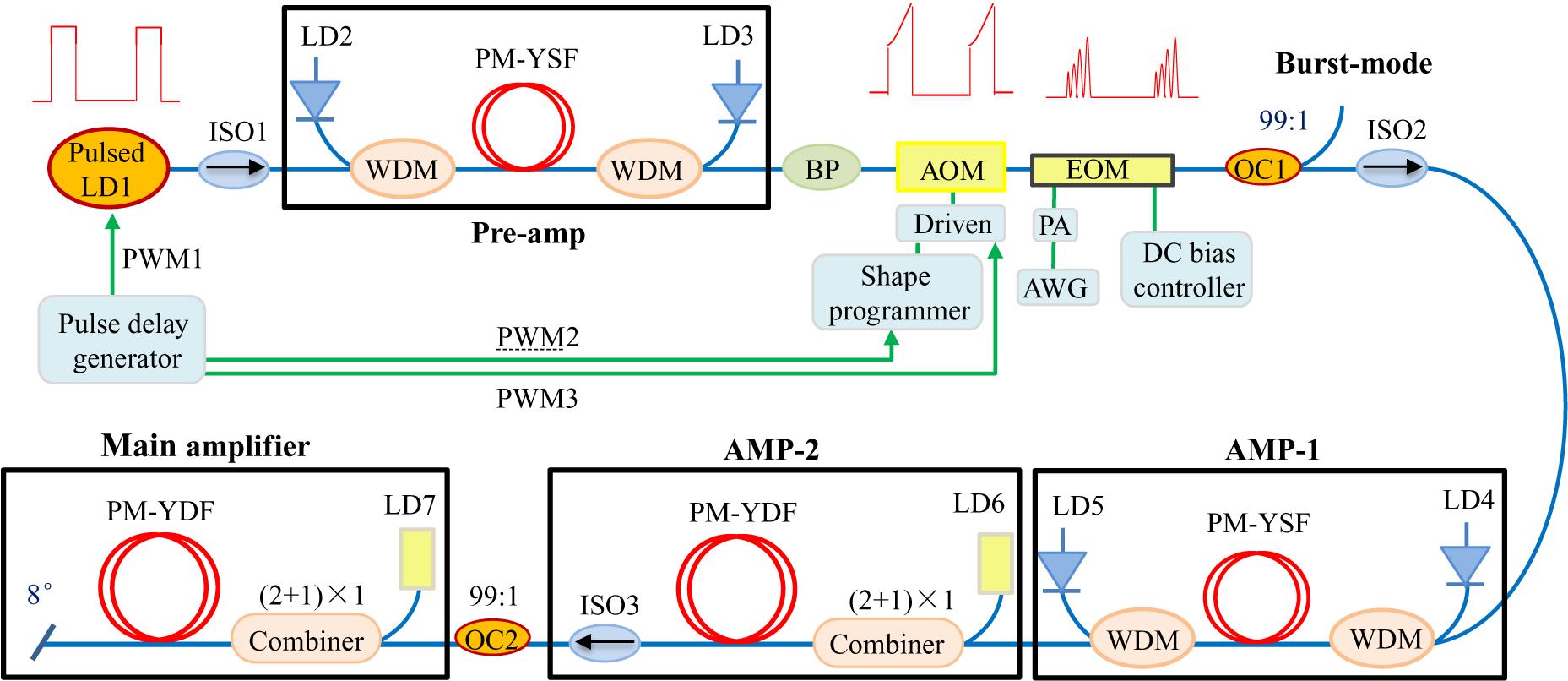
Figure 1.Schema of the linear-polarization burst-mode all-fibre laser system.
The burst-mode seed laser is amplified by a three-stage all-fibre amplifier (AMP). AMP-1 consists of 2 m highly Yb3+-doped single-cladding PM fibre (core/cladding diameter 6/125 μm) bi-directional pumped by two 976 nm LDs through the WDMs. AMP-2 is constructed from 4.5 m Yb3+-doped double-cladding PM fibre (core/cladding diameter 10/125 μm, cladding absorption of 4.8 dB/m at 975 nm) pumped by a 976 nm multi-mode LD through a (2+1)×1 signal–pump combiner. Finally, the burst-mode laser is injected into the main amplifier after an isolator (ISO3) and a coupler (coupling ratio: 1:99). The 1% port is adopted to monitor the backward power, spectrum and temporal profiles for judging the occurrence of the SBS effect. The main amplifier consists of an optimized length of 1.2 m highly Yb3+-doped double-cladding PM fibre (core/cladding diameter 20/125 μm, core numerical aperture (NA) 0.08, core absorption coefficient ∼28 dB/m at 976 nm) pumped by a 976 nm multi-mode LD through a (2+1)×1 signal–pump combiner. The active fibre is coiled on an air-cooled aluminium spool for efficient heat dissipation, with a diameter of 8.5 cm to increase the loss of high-order mode. The output port is cleaved to 8° to resist Fresnel reflection. All the fibre-based components in the experimental setup are PM.
3. Results and discussion
3.1. Suppression of ASE noise
With continuous pumping and 20 μs inter-burst period, the ASE signal would be increased over time and deplete the upper-level population until the signal burst arrives. Therefore, the ASE signal between pulses is quasi-continuous in the time domain. The ASE signal generated in the first amplifier would also be amplified in the next stage. Spectral filters could block the out-band ASE. However, some ASE would be within the wavelength band of signal which could be turned off in the time domain. After the pre-amplifier, most of the ASE noise is filtered by the 2 nm band-pass (BP) filter first, as shown in Figure 2(a), the short-wavelength near 1030 nm ASE is totally blocked and the in-band signal-to-ASE noise ratio is 40 dB. However, the inter-burst ASE could not be completely removed only by a spectrum filtering method. For testing the rest of ASE, the synchronous PWM3 is set to turn off the burst pulse. The residual ASE power is 0.05 mW and the spectrum is shown in Figure 2(a) as a red line. To turn off the inter-burst ASE using a temporal method and further improve the signal-to-ASE noise ratio, the synchronous PWM3 is set at a high voltage level of 100 ns and only the burst laser is turned on, with the corresponding spectrum shown in Figure 2(b) as a red line; it should be noted that the inter-burst ASE noise is efficiently turned off and the signal-to-ASE noise ratio is as high as 52 dB.
![]()
Figure 2.Spectrum of the burst seed after the suppression of ASE. (a) The seed burst spectrum with the 2 nm BP filter (blue dotted line) and ASE spectrum after turning off the signal (red solid line). (b) The seed burst spectrum with the 2 nm BP filter and burst seed spectrum after turning off inter-burst ASE.
3.2. Characteristics of the burst-mode fibre laser
The burst-mode laser pulse output from the EOM is regarded as the seed and the temporal waveform of the 1 GHz modulation frequency is described in Figure 3(a). The average modulation depth is equal to 73% as the modulation depth defined as dM = (Vmax − Vmin)/ (Vmax + Vmin), where Vmax and Vmin are the maximum value and the minimum value of the optical–electric signal, respectively[6]. Figure 3(b) depicts the local intra-burst pulse and the setup sine signal in detail, which shows that the intra-burst pulse is a stable sine format.
![]()
Figure 3.Seed-burst temporal shape. (a) Single-burst temporal shape. (b) Comparison between tested intra-burst pulse and sine waveform in detail.
Based on the three-stage amplifier, the burst-mode seed laser is first amplified to an average power of ~100 mW. Then, the average power is boosted to 0.8 W in the second amplifier after the IOS3. Through the power amplifier, the output average power is increased to 10 W. The temporal properties of the final output burst-mode laser are shown in Figure 4(a) which shows that serious temporal distortion of the burst envelope appears owing to the gain saturation effect. By integrating the waveform data recorded by the oscilloscope, which is equal to the pulse energy, the peak power of the frontier edge is calculated to be approximately 9 kW.
![]()
Figure 4.Pre-compensation burst-mode laser. (a) The distorted temporal profile of the amplified burst-mode laser. (b) The calculated transfer function
To decrease the envelope distortion induced by the gain saturation effect, a pre-compensation technique is adopted to realize the homogenous energy distribution in each burst by the AOM. Figure 4(a) shows the amplified burst temporal shape of the no-compensation burst-mode seed laser (shown in Figure 3(a)) output from the three-stage amplifier. The transfer function G(t) can be calculated from the input and output pulse intensities as depicted in Figure 4(b). The pulse leading-edge and trailing-edge gain coefficients of the transfer function are G(t) = 39.4 dB and G(t)|t=100 ns = 32.9 dB, respectively. The pre-compensated burst temporal shape can be calculated based on the exponential function Iout(t) = Iin(t) × (1 – G0) exp[–Eout(t)/Esat] as shown in Figure 4(c). As a result, the output homogenous energy distribution of the burst envelope is shown in Figure 4(d), the average power of which is 10 W, yielding maximum burst energy of 200 μJ, i.e., 2 μJ per intra-sine pulse, corresponding to a peak power of 4 kW. The average intra-burst modulation depth is changed as 0.95 owing to small signal gain amplifier profile.
The output power and the backward power versus pump power in the main amplifier are also shown in Figure 5(a), which indicates that the output power increases linearly at a slope efficiency of 52%, and the backward power increases gradually with pump power. When the maximum output power arrives at 10.1 W, some backward Stokes pulse spike is observed at the 1% port of OC2. The tested backward power is 114 μW, corresponding to 11.4 mW backward propagated light power, which is a little higher than 0.1% of the output power regarded as the threshold of the SBS effect. The SBS is generally the primary limiting factor for the power scaling of the narrow-linewidth fibre laser. The spectra of the injected seed (blue solid line) and the laser at maximum output power (red dotted line) are shown in Figure 5(b). The 3 dB linewidth of the burst laser at maximum output is only approximately 0.19 nm. It is noted that no residual pump light is observed and the intensity of the signal light is about 48 dB higher than that of the ASE signal, which indicates that the ASE signal can be neglected.
![]()
Figure 5.Output characterizations. (a) The output power and backward power versus pump power. (b) The output spectrum of injected seed and maximum output. (c) The RF spectrum. (d) The polarization degree versus different pump power.
As shown in Figure 5(c), the corresponding RF spectrum is centred at 1.0 GHz with a 3 dB bandwidth of 10 MHz, which indicates the intra-burst repetition rate of 1 GHz and the burst duration of 100 ns. The local RF spectrum depicts that the repetition rate of the burst envelope is 50 kHz. In addition, the polarization degree is measured with a λ/2 waveplate and a polarization beam splitter as shown in Figure 5(d), defined as P1/(P1 + P2), where P1 and P2 are the main and minor polarization state power, respectively. The polarization degree is higher than 95.6% indicating the excellent and stable polarization quality of this laser system.
3.3. Frequency-adjustable microwave generation
The experimental scheme of the frequency-adjustable microwave signal generation based on a linear-state PCSS is illustrated in Figure 6. The material of the PCSS is V-doped 6H-SiC[8], which can be excited efficiently by 1064 nm light owing to the deep acceptor level of 0.7 eV. The V doping can compensate for the unintentional shallow p-type impurities in 6H-SiC to achieve a semi-insulating state, which is in accordance with the tested high dark resistivity of approximately 1012 Ω/cm without light illumination. The thickness of the 6H-SiC wafer is 200 μm, which is chosen by considering the breakdown voltages and the conducting resistance. The bias voltage hold capacity is higher than 10 kV with the help of high-intensity packing with epoxy to fill the PCSS as it has a relatively high dielectric constant. The upper surface is coated with AZO (aluminium-doped ZnO) to form a transparent electrode. The opposite surface is coated with a silver film to reflect the light back to the PCSS material again and increase the absorbed light energy. In the experiment, the reflection coefficient and the absorption coefficient are 0.2 and 80 m–1, respectively. The burst-mode laser is collimated and expanded to a radius of 3 mm, and then illuminated to the transparent electrode of the PCSS. In the circuit, a 100 Ω load resistor is in series with the PCSS and a capacitor is discharged between them. The output photocurrent is detected by a current viewing resistor (CVR) with an internal resistance of 0.1 Ω and a rise time of 0.18 ns. The temporal and frequency data are acquired by an Agilent oscilloscope with bandwidth of 13 GHz and sampling rate of 40 GS/s.
![]()
Figure 6.Scheme of frequency-adjustable microwave signal generation based on the linear-state PCSS.
The generated current value of the PCSS could be measured by the CVR and the corresponding power of the microwave signal is equivalently calculated as P = UI, where U is the voltage at both ends of the PCSS device and I is the generated current. In the experiment, the intra-burst repetition rate of the burst laser is adjusted from 0.8 to 1.12 GHz as shown in Figures 7(a)–7(c). The corresponding parallel voltages of the CVR are measured and shown in Figures 7(d)–7(f). The measured oscillating parallel voltage of the CVR is approximately 3 mV, i.e., the radiation peak power of this system is 300 W under a 10 kV bias voltage. In addition, the burst duration of the generated microwave signals is 100 ns, which is the same as that of the irradiated burst laser. Similar to the RF spectrum of the burst laser, which is shown in Figure 5(c), the 3 dB bandwidth of the generated microwave signals should also be 10 MHz, which indicates that the signals are narrowband. In addition, the corresponding RF spectra with a frequency scale of 2.5 GHz are measured. As shown in Figures 7(g)–7(i), the frequencies of the generated microwave signal are 0.8, 1 and 1.12 GHz, respectively, and the ratios of the signal to second harmonic noise are all larger than 25 dB. The PCSS indeed has a fast response and operates in linear mode, and the rectangular envelope of burst-mode laser assures the uniform energy radiation of the microwave during the illumination.
![]()
Figure 7.Experimental results of the generated frequency-adjustable microwave signal. (a)–(c) The temporal profile of burst-mode laser with different repetition rates of 0.8, 1 and 1.12 GHz, respectively. (d)–(f) The corresponding measured voltages of CVR. (g)–(i) The corresponding RF spectrum.
4. Conclusion
In this paper, a linear-polarization burst-mode all-fibre laser with sinusoidal intra-burst waveform has been demonstrated to generate the high-power frequency-adjustable microwave signal based on the linear-state PCSS for the first time. The continuous ASE noise in the pre-amplifier is turned off by the AOM, and a pre-compensation technique is applied to achieve the homogenous energy distribution in the burst after the main amplifier. The maximum burst energy reaches 200 μJ with a burst duration of 100 ns at an average power of 10 W, and the corresponding peak power is 4 kW. When the linear-state PCSS is illuminated by the burst-mode laser, up to 300 W, a narrowband frequency-adjustable microwave signal of 0.80–1.12 GHz is realized.
References
[1] J. Capmany, D. Novak. Nat. Photonics, 1, 319(2007).
[2] D. Marpaung, J. Yao, J. Capmany. Nat. Photonics, 13, 80(2019).
[3] M. H. Khan, H. Shen, Y. Xuan, L. Zhao, S. Xiao, D. E. Leaird, A. M. Weiner, M. Qi. Nat. Photonics, 4, 117(2010).
[4] S. Putz, A. Angerer, D. O. Krimer, R. Glattauer, W. J. Munro, S. Rotter, J. Schmiedmayer, J. Majer. Nat. Photonics, 11, 36(2017).
[5] J. D. McKinney, D. E. Leaird, A. M. Weiner. Opt. Lett., 27, 1345(2002).
[6] L. Huang, L. Li, P. Ma, X. Wang, P. Zhou. Opt. Express, 24, 26722(2016).
[7] J. Zhang, D. Zhang, Y. Fan, J. He, X. Ge, X. Zhang, J. Ju, T. Xun. Phys. Plasmas, 27, 010501(2020).
[8] Q. Wu, T. Xun, Y. Zhao, H. Yang, W. Huang. IEEE Trans. Electron Devices, 66, 1837(2019).
[9] O. S. F. Zucker, P. K. Yu, A. Griffin. IEEE Trans. Electron Devices, 42, 1285(2014).
[10] J. Y. Tsao, S. Chowdhury, M. A. Hollis, D. Jena, N. M. Johnson, K. A. Jones, R. J. Kaplar, S. Rajan, C. G. Van de Walle, E. Bellotti, C. L. Chua, R. Collazo, M. E. Coltrin, J. A. Cooper, K. R. Evans, S. Graham, T. A. Grotjohn, E. R. Heller, M. Higashiwaki, M. S. Islam, P. W. Juodawlkis, M. A. Khan, A. D. Koehler, J. H. Leach, U. K. Mishra, R. J. Nemanich, R. C. N. Pilawa-Podgurski, J. B. Shealy, Z. Sitar, M. J. Tadjer, A. F. Witulski, M. Wraback, J. A. Simmons. Adv. Electron. Mater., 4, 1600501(2018).
[11] H. Kalaycıoğlu, P. Elahi, Ö. Akçaalan, F. Ö. Ilday. IEEE J. Sel. Top. Quantum Electron., 24, 8800312(2018).
[12] S. Roy, N. Jiang, P. S. Hsu, T. Yi, M. N. Slipchenko, J. J. Felver, J. Estevadeordal, J. R. Gord. Opt. Lett., 43, 2704(2018).
[13] S. Rezaei, J. Li, P. R. Herman. Opt. Lett., 40, 2064(2015).
[14] N. Ma, M. Chen, C. Yang, S. Lu, X. Zhang, X. Du. High Power Laser. Sci. Eng., 8, e1(2020).
[15] M. N. Zervas, C. A. Codemard. IEEE J. Sel. Top. Quantum Electron., 20, 219(2014).
[16] T. Chen, H. Liu, W. Kong, R. Shu. Opt. Express, 24, 20963(2016).
[17] H. Kalaycioglu, K. Eken, F. Ö. Ilday. Opt. Lett., 36, 3383(2011).
[18] J. Petelin, B. Podobnik, R. Petkovšek. Appl. Opt., 54, 4629(2015).
[19] D. Marion, J. Lhermite, L. Pontagnier, A. Aubourg, P. Héricourt, G. Santarelli, E. CormierLaser Congress 2018 (ASSL). , , , , , , and , in (Optical Society of America, 2018), paper ATh5A.5..
[20] M. Nie, X. Cao, Q. Liu, E. Ji, X. Fu. Opt. Express, 25, 13557(2017).


Set citation alerts for the article
Please enter your email address

© Copyright 2018-2021 | Chinese Laser Press. All Rights Reserved 沪ICP备15018463号-20