
Zhibiao Zhu, Yongfeng Li, Zhe Qin, Lixin Jiang, Wenjie Wang, Hongya Chen, Jiafu Wang, Yongqiang Pang, Shaobo Qu, "Miura origami based reconfigurable polarization converter for multifunctional control of electromagnetic waves," Photonics Res. 12, 581 (2024)
- Photonics Research
- Vol. 12, Issue 3, 581 (2024)
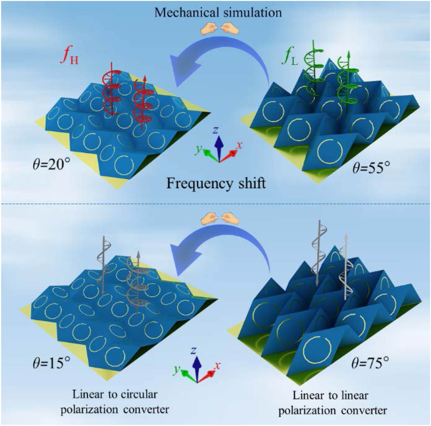
Fig. 1. Polarization converter based on Miura origami can achieve multiple functional control of EM waves. First, in different folding states of origami, the polarization converter operates at different frequencies. In addition, by adjusting the folding angle of the origami structure, linear-to-linear and linear-to-circular polarization converters can be realized under the incidence of linear polarization waves, respectively.
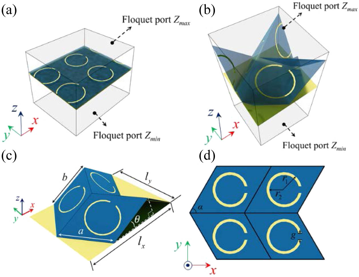
Fig. 2. (a) Simulation setting of planar origami polarization converter (θ = 0 ° θ ≠ 0 °
Fig. 3. (a) Simulated reflection spectra of the origami polarization converter. The surface current distributions on metallic parts under y θ = 15 ° θ = 35 ° θ = 55 °
Fig. 4. (a) Sketch of the polarization azimuth angle α β y θ f = 3.1 GHz ψ = 45 ° α β
Fig. 5. (a) When the folding angle θ = 15 ° x y f = 3.1 GHz x y θ = 75 ° x y f = 3.1 GHz x y
Fig. 6. (a) Measurement experimental setup in microwave anechoic chamber. (b) Measured and simulated reflection spectra of the origami polarization converter under different folding states (θ = 15 ° θ = 15 ° x y θ = 75 ° x y


Set citation alerts for the article
Please enter your email address

© Copyright 2018-2021 | Chinese Laser Press. All Rights Reserved 沪ICP备15018463号-20