【AIGC One Sentence Reading】:This paper introduces a Miura origami-based polarization converter, offering enhanced flexibility and cost-effectiveness in manipulating electromagnetic waves through mechanical control, enabling linear-to-linear and linear-to-circular polarization conversions.
【AIGC Short Abstract】:This paper introduces a novel, Miura origami-based polarization converter that offers enhanced control over electromagnetic waves. By adjusting the folding angle, it tunes the operating frequency and reflected wave polarization, adding more manipulative freedom. Lightweight, low-cost, and versatile, this design paves the way for reconfigurable linear polarization conversion and multifunctional devices.
Note: This section is automatically generated by AI . The website and platform operators shall not be liable for any commercial or legal consequences arising from your use of AI generated content on this website. Please be aware of this.
Abstract
Polarization is one of the basic characteristics of electromagnetic (EM) waves, and its flexible control is very important in many practical applications. At present, most of the multifunction polarization metasurfaces are electrically tunable based on PIN and varactor diodes, which are easy to operate and have strong real-time performance. However, there are still some problems in them, such as few degrees of freedom of planar structure control, complex circuit, bulky sample, and high cost. In view of these shortcomings, this paper proposes a Miura origami based reconfigurable polarization conversion metasurface for multifunctional control of EM waves. The interaction between the electric dipoles is changed by adjusting the folding angle , thereby tuning the operating frequency of the polarization conversion and the polarization state of the reflected wave. This mechanical control method brings more degrees of freedom to manipulate EM waves. And the processed sample is with lightweight and low cost. To verify the performance of the proposed origami polarization converter, a Miura origami structure loaded with metal split rings is designed and fabricated. The operating frequency of the structure can be tuned in different folding states. In addition, by controlling the folding angle , linear-to-linear and linear-to-circular polarization converters can be realized at different folding states. The proposed Miura origami polarization conversion metasurface provides a new idea for reconfigurable linear polarization conversion and multifunctional devices.
1. INTRODUCTION
Recently, metasurfaces have developed into a new research field. Metasurfaces can be designed to be materials with arbitrary permittivity and permeability, manipulating electromagnetic (EM) waves in ways that have never been possible before. In addition, metasurfaces are gradually developing new structural forms, which can achieve more and more diverse functions. Examples include holography, vortex beams for wireless communication systems [1], radar cross section (RCS) reduction [2], focusing [3–6], and polarization conversion [7–17]. Polarization is one of the important characteristics of EM waves, which can be applied to communication and radar systems [18]. Polarization clearly has significant research value. Polarization conversion metasurfaces experienced the development process of passive and active polarization conversion metasurfaces. They are classified into two types: reflection type and transmission type polarization conversion metasurfaces. These polarization conversion metasurfaces enable functions such as linear to linear [19], linear to circular [7], and circular to circular [20] conversions. For the active polarization conversion metasurface, the switching between polarization conversion functions can be realized.
With the development of intelligent technology in recent years, metasurfaces are required to flexibly control EM waves by sensing environmental changes and reconfiguring structural elements. The active metasurface uses a varactor diode, PIN diode, and variable resistance diode to electrically control the parameters. For example, Tian et al. [21] used PIN diodes as switches to realize real-time and fast conversion of linear-to-linear polarization and linear-to-circular polarization in 2019. The method of active metasurface to realize related functions is simple, but the limitations of complex circuits and high cost make it unable to be better utilized in a large area in practical application scenarios. In addition, the control degrees of freedom (DOF) of active metasurfaces are related to the number and type of active devices. When the control DOF of active metasurfaces increases, the complexity of the structure and the number of devices increase. Thus, the cost increases significantly.
The emergence of paper-cut/origami metamaterials [22–25] has solved the above problems and achieved lightweight structure while achieving multi-DOF control. Origami is a very promising technique for realizing reconfigurable metamaterials. This is the ancient art of folding a piece of paper into a complex and delicate 3D object. In recent years, origami technology has attracted great interest from scientists and engineers due to its ability to create materials with various shape variations. Origami has excellent mechanical properties and provides more control freedom. In recent years, origami has been gradually applied to the EM field. By changing the folding state of origami and loading the origami structure of metallic patterns, different functions are realized. For example, Li et al. [24] proposed a multifunctional metamaterial based on Miura origami, which realized three functions of the absorber, mirror reflector, and negative reflector by changing the folding angle. Le et al. [25] proposed a multifunctional metamaterial based on paper-cut metamaterials, which changed the folding state of paper folding through mechanical stimulation, so as to realize three functions: a bandpass filter, absorber, and reflector. Wang et al. [26] reported a metamaterial based on Miura origami, which results in a strong chiral response by deforming the origami structure. However, few scientists have reported in detail how origami modulates the polarization of EM waves.
Sign up for Photonics Research TOC. Get the latest issue of Photonics Research delivered right to you!Sign up now
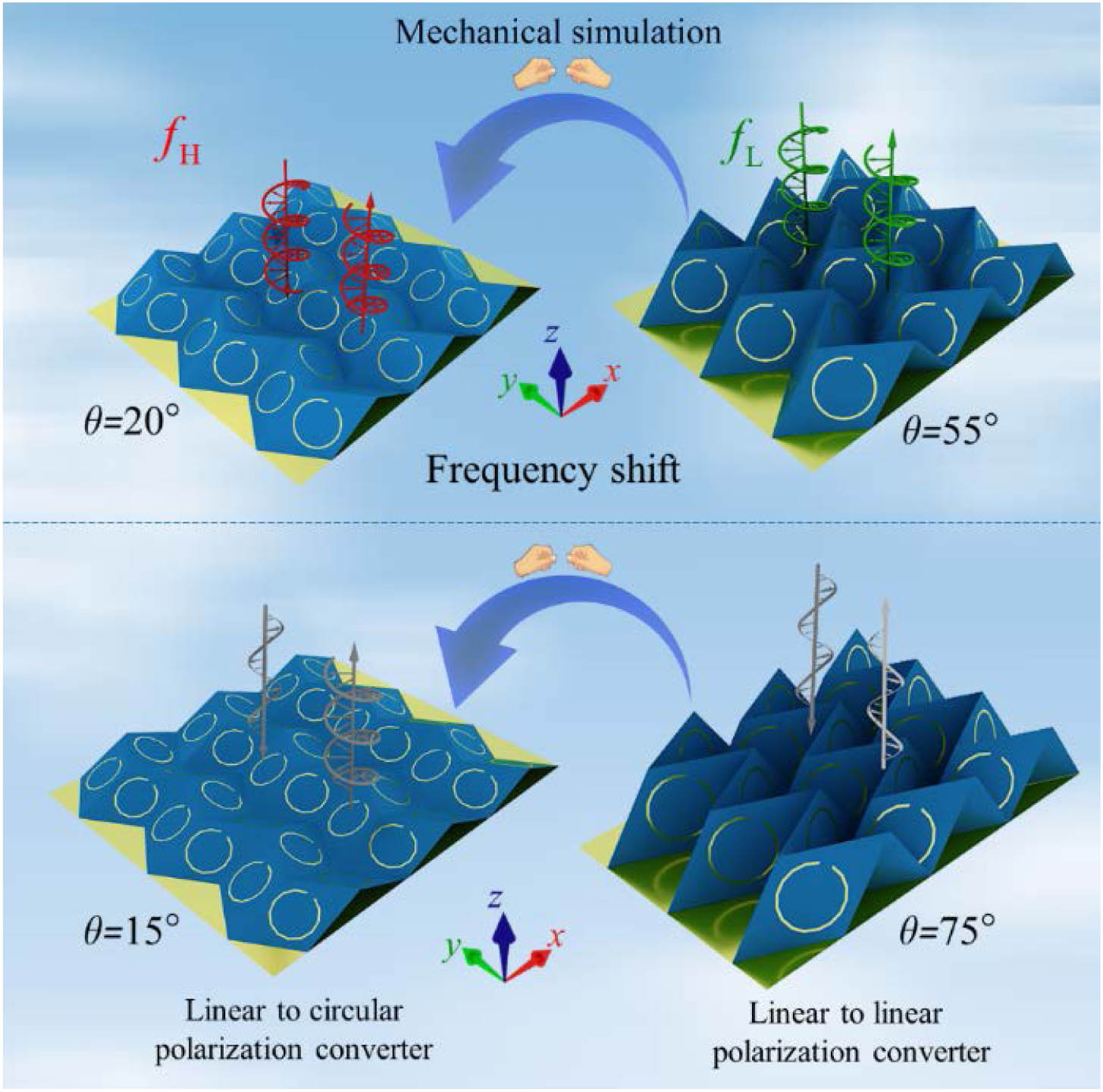
In this paper, a reconfigurable polarization conversion metasurface based on Miura origami is designed for multifunctional control of EM waves. Among the origami types, Miura origami is chosen for the following reasons: the reconfigurability of the continuous state range and the large surface reconfigurable property of folding to unfolded state. The fabricated Miura origami substrate is loaded with metallic split rings. The shape of Miura origami is regulated by mechanical stimulation. After changing the folding angle of the origami structure, the interaction between the electric dipoles on the surface of the structure changes accordingly. Thus, the multifunctional control of EM waves is realized by the structure, as shown in Fig. 1. One function of the origami polarization conversion metasurface is that the operating frequency of polarization conversion can shift when the folding angle is changed. In addition, the origami polarization conversion metasurface can also control the polarization state of the reflected EM wave. When the folding angle is , the origami polarization conversion metasurface can be regarded as a linear-to-circular polarization converter. When the folding angle is , this origami polarization conversion metasurface can be regarded as a linear-to-linear polarization converter. The proposed polarization conversion metasurface achieves multifunctional control of EM waves under the premise of lightweight structure and low processing cost. This provides reference for the development of multifunctional metasurfaces in the future.
Figure 1.Polarization converter based on Miura origami can achieve multiple functional control of EM waves. First, in different folding states of origami, the polarization converter operates at different frequencies. In addition, by adjusting the folding angle of the origami structure, linear-to-linear and linear-to-circular polarization converters can be realized under the incidence of linear polarization waves, respectively.
CST full-wave simulation software is used to simulate the EM response of the origami polarization converter. The simulation process is as follows. (i) CST solver is set as frequency domain solver. (ii) The frequency range is set as 0–5 GHz. (iii) We set two Floquet port modes, and both ports are linearly polarized wave excitation in different folding states of the structure. (iv) Periodic boundaries are set in the and directions, and open (added space) boundaries are set in the and directions. After setting the simulation conditions, the model is established according to the structural relations of Miura origami. In order to reduce the computational cost of simulation, we redefined the unit cell, as shown in Figs. 2(a) and 2(b). We intercept the period of a rectangle on consecutive adjacent Miura origami structures. As the structure is designed to work under reflective conditions, there is a metal back plate on the bottom of the origami. The air gap exists between the metal back plate and the origami polarization converter, with a thickness of . In the experimental stage, this layer of air gap is replaced with foam.
Figure 2.(a) Simulation setting of planar origami polarization converter (). (b) Simulation setting of nonplanar origami polarization converter (). (c) Structural parameters of Miura origami substrate. (d) Dimension parameters of metallic split ring.
The unit cell of the origami polarization converter is composed of four symmetrical parallelograms arranged periodically. For convenience, the elements of each parallelogram are called facets. The facet design parameters are shown in Figs. 2(c) and 2(d). The geometric parameters of the facet are , . The outside diameter of the split ring is . The inside diameter of the ring is . The width of opening is . The folding state of the reconfigurable polarization converter is determined by the folding angle . When , the origami polarization converter is in the flat state. When gradually increases, the lengths of the parameters and change accordingly. In the following formula, and can be represented by as [22] where . and are the length parameters of the unit mentioned above. By changing the folding angle , and change in size. A foldable polarization converter is investigated without tearing or stretching the substrate. It is worth noting that there are several parameters that determine the folding state of origami. In order to ensure that the desired frequency converges at the desired location, there can only be one variable () that describes the folded state of the origami polarization converter. The frequency shift caused by change of the is calculated as follows: where is the frequency shift produced by changing to from , and is the midpoint frequency between and .
As shown in Fig. 3(a), as the folding angle of origami polarization converter increases, the working frequency gradually moves to low frequency (, , and ). In addition, the physical mechanism of operating frequency migration is discussed by analyzing the surface current distribution of metallic patterns, as illustrated in Figs. 3(b)–3(d). When the origami structure is in any folded state, the surface currents on both arms of the split ring oscillate back and forth along the metallic arms. Remarkably, the current oscillates in the same direction on both arms. Thus, surface currents on each metallic spilt ring can be equivalent to the electric dipole. Four metallic spilt rings are equivalent to four electric dipoles (, , , and ). For example, for and , the interaction energy between them is . As the folding angle increases, the distance between the electric dipoles and decreases. In this case, the strength of the surface current on the metallic rings increases. When the folding angle is , the surface currents on the split rings are weak and the attraction between the dipoles is weak, as shown in Fig. 3(b). The origami polarization converter works in the high frequency band (). As the folding angle increases, the surface currents on the split rings gradually strengthen [Figs. 3(c) and 3(d)]. The two dipoles on the origami surface become more attractive to each other, making the system more stable. As a result, the operating frequency is shifted to lower frequencies ( and ). The analysis of other electric dipole groups is similar.
Figure 3.(a) Simulated reflection spectra of the origami polarization converter. The surface current distributions on metallic parts under -polarization incidence: (b) , (c) , and (d) .
Polarization is the phenomenon that the electric field vector of EM wave vibrates according to a certain law. Based on EM field theory, this paper analyzes the basic principle of circular polarization conversion and resonant frequency regulation after the EM wave incident on the origami structure. This provides the basis and guidance for the final design. Aiming at the polarization conversion efficiency of the origami circular polarization converter, we assume that a -polarized EM wave is incident on the surface of the structure from the direction. Hence, the electric field of the incident EM wave can be expressed as . Furthermore, the electric field of the reflected wave can be expressed as [27] where and , and and are the amplitudes of reflection cofficients and . Additionally, and are the phases of reflection waves. Then, and are used to denote the reflection efficiency of linear-to-circular polarization. and represent the corresponding reflection amplitude. and represent the corresponding phase of reflection. Meanwhile, the reflected electric field of LCP and RCP waves can be expressed as
It is worth noting that . Combined with the above formula, the following formulas are deduced:
It can be found that the amplitudes of reflection coefficients of co-polarization and cross-polarization should be equal and as high as possible to achieve an effective conversion from linear polarization to circular polarization. At the same time, the phase difference between the co- and cross-polarization reflection coefficients is ( is an integer). To study the polarization of reflected waves, four Stokes parameters are introduced as follows:
As shown in Fig. 4(a), polarization azimuth and ellipticity describe the orientation of the principal axis of the ellipse and the shape of the ellipse. They can be obtained by the following formula:
Figure 4.(a) Sketch of the polarization azimuth angle and the ellipticity angle . (b) Co- and cross-polarized reflection amplitudes and phase difference between them under - polarized wave incidence. The folding angle changes from 15° to 75° (, ). (c) Calculated azimuth angle and the ellipticity angle at different folding angles. (d) Polarization ellipses of the reflected wave at different folding angles (75°, 65°, 55°, 45°, 30°, and 15°).
Figure 4(b) describes the changes of and amplitudes when the folding angle changes from 15° to 75° (, ). Meanwhile, the phase difference between the two reflected waves remains the same, which is 90°. According to Eqs. (9) and (10), the result shown in Fig. 4(c) can be obtained. The above derivation shows that when the folding angle of the origami structure changes, the polarization ellipticity angle at can be adjusted from 0° to 45° (). The azimuth angle of polarization remains constant when the folding angle changes. Therefore, when the origami structure is dynamically regulated, the control from linear polarization to circular polarization can be realized under the -polarized wave incidence. Figure 4(d) shows the polarization states of the polarization ellipse under different folding angles. When the folding angle , the reflected wave is a linearly polarized wave. When the folding angle , the reflected wave is a circularly polarized wave. When , the ellipticity angle changes with the fold angle .
By analyzing the surface current distribution, the physical mechanism of polarization conversion under a different folding state of the structure is discussed. Decompose the electric field vector () into the vertical directions and , as shown in Fig. 4(c). Then, the commercial simulation software CST is used to obtain the simulation results of the surface current distribution under the incidence of -polarized and -polarized waves. Figure 5 shows the surface current distribution of the metallic spilt ring under two folding angles ( and ) at . Under the incident of or polarized wave, strong surface currents are generated on the surface of the metallic split ring. And the surface currents on the two arms oscillate back and forth in the same direction. Therefore, the surface currents on the four split rings can be equivalent to four electric dipoles (, 2, 3, 4). According to Ref. [26], the total effective electric dipole is . In addition, according to the calculation formula in Ref. [28], the total effective electric dipoles of the four electric dipoles have zero components in the and directions. It can be concluded that . Therefore, the total effective electric dipole can be equivalent to an electric dipole in the direction.
Figure 5.(a) When the folding angle , the co-polarized reflection amplitudes and phases at 3.1 GHz under - and -polarized wave incidence. Current distributions on the surface of the metallic split ring at folding angle 15° (), under two linearly polarized incident waves: (b) -polarization incidence, (c) -polarization incidence. (d) When the folding angle , the co-polarized reflection amplitudes and phases at 3.1 GHz under - and -polarized wave incidence. Current distributions on the surface of the metallic split ring at folding angle 75° (), under two linearly polarized incident waves: (e) -polarization incidence, (f) -polarization incidence.
When the folding angle , the two total effective dipoles and in the direction radiate and polarized waves, respectively, with a phase difference of 90° and an equal amplitude (). As shown in Figs. 5(b) and 5(c), in this case, the surface currents are strong under both - and -polarized waves. Polarization conversion occurs for both incident linearly polarized waves. Therefore, both and incident polarized waves undergo polarization conversion of 90°, and a circularly polarized wave is synthesized after the polarization conversion. As shown in Fig. 5(d), the total effective electric dipoles and emit - and -polarized waves, respectively. The phase difference of the two linearly polarized waves is 180°, and the amplitude is equal (). As shown in Figs. 5(e) and 5(f), when the folding angle , the surface currents are strong under -polarized wave irradiation, and the incident -polarized wave undergoes 90° polarization conversion. When illuminated by -polarized waves, the surface current is weak and no polarization conversion occurs for the incident wave. It can be concluded that at the folding angle , the incident -polarized wave undergoes polarization conversion. And it combines with another outgoing -polarized wave into a linearly polarized wave in the same direction.
4. FABRICATION AND MEASUREMENT
To verify the feasibility of the reconfigurable origami polarization converter, a sample is fabricated and measured, as shown in Fig. 6(a). In the sample processing link, the metallic split rings are printed on the cut polyimide films. Subsequently, the numerical control is used to etch creases on the polypropylene (PP) material substrate with a thickness of 0.05 mm. Finally, the polyimide films are pasted on the PP material substrate. The experimental setup consists of a pair of linearly polarized wideband horn antennas operating in the frequency range 2–18 GHz. In this pair of antennas, one is used as the transmitting antenna and the other is used as the receiving antenna. Meanwhile, the two antennas are connected to the two interfaces of the vector network analyzer to obtain more accurate analysis results. In addition, to minimize the impact of test noise, the measurements are chosen to perform in a microwave anechoic chamber. When setting up the antenna, the transmitting and receiving antennas are placed in a symmetric manner. Moreover, this set of antennas should have some space from the origami polarization converter under test. Setting the transmitting and receiving antennas at the same height allows the EM waves emitted by the transmitting antenna to be more effectively reflected by the origami device. At the same time, it ensures that the receiving antenna can fully receive the reflected EM waves, thus increasing the accuracy of the test results.
Figure 6.(a) Measurement experimental setup in microwave anechoic chamber. (b) Measured and simulated reflection spectra of the origami polarization converter under different folding states (, 30°, and 55°). (c) When the folding angle , the measured co-polarized reflection amplitudes and phases at 3.1 GHz under - and -polarized wave incidence. (d) When the folding angle , the measured co-polarized reflection amplitudes and phases at 3.1 GHz under - and -polarized wave incidence.
As shown in Fig. 6(b), during the test, as the folding angle of the origami polarization converter continues to increase, the working frequency of the structure continues to move to low frequency. In addition, Fig. 6(c) shows that when the folding angle of the origination is 15°, the phase difference between the - and the -polarized waves remains 90° around 3.1 GHz. The reflection amplitude of both linearly polarized waves is close to one. Therefore, in this folded state, the reflected wave is circularly polarized. Figure 6(d) shows that when the folding angle of the origination is 75°, the phase difference between the - and the -polarized waves remains 180° around 3.1 GHz. The reflection amplitude of both linearly polarized waves is close to 1. Therefore, in this folded state, the reflected wave is linearly polarized. Since a flexible material is chosen as the substrate, the structure is not strictly rigid. And the deformation between different folded Miura origami structural elements may be slightly different. In addition, the experimental environment can also lead to differences between the experimental and the simulation results.
5. CONCLUSION
In summary, we propose a reconfigurable polarization conversion metasurface based on Miura origami. The surface current distribution simulation results show that the interaction between the electric dipoles can be changed by adjusting the folding angle , so as to tune the operating frequency of polarization conversion and the polarization state of the reflected wave. In addition, by controlling the folding angle , linear-to-linear and linear-to-circular polarization converters can be realized in different folding states. Compared with other polarization converters, this mechanical control method brings more DOFs to manipulate the EM wave. To verify the performance of the proposed origami polarization converter, a Miura origami polarization converter loaded with metal split rings is designed and fabricated. The processed samples are with lightweight and low cost. The proposed Miura origami polarization conversion metasurface provides a new idea for the design of reconfigurable antennas and multifunctional devices in the future.
 AI Video Guide
  AI Picture Guide
 AI One Sentence