Yixiao Zhu, Fan Zhang. Solving characteristic equation of orbital angular momentum modes in a ring fiber[J]. Chinese Optics Letters, 2015, 13(3): 030501
Copy Citation Text
The characteristic equation of orbital angular momentum modes in a ring fiber is derived. By solving the equation with the graphical method, mode distribution in a ring fiber can be precisely determined for arbitrary fiber parameters without relying on simulation of the vector field. This will provide a useful method to determine the separation between quasi-degenerate modes in a ring fiber.
Light beams carrying orbital angular momentum (OAM) are characterized as a spiral phase structure of , where is topological charge (an integer), and is the azimuthal angle[1,2]. The OAM modes with different topological charge number are inherently orthogonal to each other, and therefore can be considered as an additional available degree of freedom for multiplexing information[1,3]. Combining OAM with other traditional multiplexing technologies such as wavelength division multiplexing (WDM), the capacity and spectral efficiency of optical communication systems will be greatly enhanced[3–5].
Although there have been several reports for free-space transmission based on OAM[3,5,6], transmission in fiber can avoid atmospheric disturbance[7], and make long-distance transmission feasible. However, OAM modes are unstable in terms of propagation in a conventional step-index fiber due to the mode coupling[2,8]. It is known that hybrid modes ( and ) are Eigen modes in a fiber. The combination of quasi-degenerate and modes results in linearly polarized (LP) modes (i.e., , ), while the combination of intrinsic degenerate and ( and ) modes with phase shift generates OAM modes [i.e., , ][8–10]. In a conventional multimode fiber, LP modes are easily produced by coupling because the effective refractive index (ERI) difference between and modes is too small[2,4,8]. To overcome this problem, several schemes were proposed such as coiling the fiber[11], using spun elliptical and anisotropic fibers[12], and the intensely twisted elliptical fiber was based on band-gap Bragg selection[13]. Nevertheless, recently more attention has been paid to the structure of a ring fiber, which splits the quasi-degenerate modes by increasing the ERI difference. The generation of a higher-order OAM mode in a ring fiber has been studied[14] and analysis of the modes has been given[15]. Then generation and multiplexing OAM modes in a ring fiber was proposed[16]. To our best knowledge, theoretical analysis of the mode properties in a ring fiber made before are all based on the weakly guiding approximation (WGA), which focus on LP modes and thus cannot show the difference between quasi-degenerate modes[17,18].
In this Letter, a modal characteristic equation is derived by rigorously solving the Helmholtz equation. Based on this characteristic equation, we investigate the influence of the ring fiber structure parameters on the ERI of the Eigenmodes. Besides, it should be noted that the exact degeneracy of two optical vortices with opposing topological charges and spin will interact each other due to infinitesimal ellipticity induced by stress[19]. However, our theory is applicable to the ideal ring fiber, and the situation where fibers are slightly elliptical deserves further study.
Sign up for Chinese Optics Letters TOC. Get the latest issue of Chinese Optics Letters delivered right to you!Sign up now
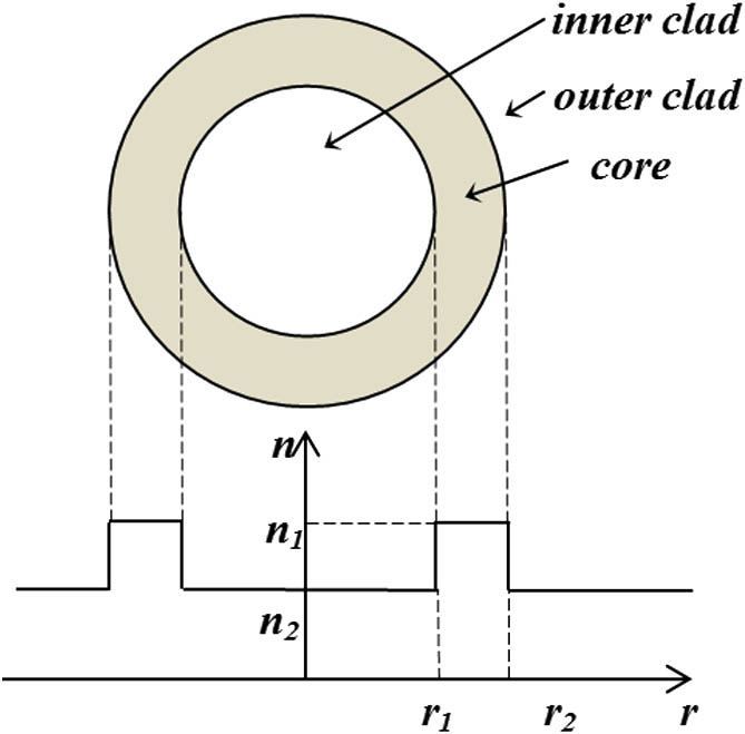
Figure 1 shows the cross section and the refractive index (RI) profile of a ring fiber. It consists of three concentric regions: the inner clad, the core, and the outer clad. The RI of the core is while the RI of the inner and outer clad are both which satisfies . The inner radius and outer radius of ring fiber are and , respectively. A cylindrical coordinates is set due to the longitude invariance and the angular symmetry of the geometry. We first deal with the longitudinal components of the electric and magnetic field by solving the Helmholtz equation[20]. where , and is the wavenumber in the corresponding regions. By applying the method of variable separation, can be written aswhere is the propagation constant along the -axis direction, is the angular frequency, and is the wavenumber in vacuum. and are Bessel functions of the first kind and the second kind, respectively. and denote the modified Bessel functions of the first kind and the second kind, respectively. The subscript is the order of the Bessel function which is an integer. The terms , , , and are constants to be determined by boundary conditions. The term of in Eq. (2) shows the total angular momentum (AM) of the Eigen modes in the ring fiber, where “” denotes that each of the modes () has two inherent degeneracies. If is set as the basis instead of for the angular part in Eq. (2), we can get the odd and the even modes as mentioned previously[9,20,21]. Note that total AM consists of both spin angular momentum (SAM) and OAM[14]. The combination of the odd and even modes with phase shift become OAM modes with a total AM of , where the OAM part is when the SAM is antiparallel with the OAM or when the SAM is parallel with the OAM. The corresponding magnetic field component can be obtained by substituting the constants , , , and for , , , and , respectively.
After and were formulized, the rest of the components , , , and can be derived from the following relations[20]where and are permeability and permittivity of the corresponding regions, respectively. In our calculation, and is adopted where and are respectively permeability and permittivity of vacuum[20].
To determine the eight constants , we apply the continuity conditions of the electromagnetic field components , , , and at the interfaces of and to obtain eight () equations. Then a nonzero solution for the set of equations requires its determinant of coefficient to equal zero[22], which is shown as Eq. (6). By using the Gauss elimination method[22], the determinant mentioned previously can be reduced to a form of Eq. (7). Here variable substitution is adopted in the following two steps.
Finally the characteristic equation of a ring fiber is obtained in Eq. (10) by expanding the determinant.
To go back into the case of the step-index fiber, the first four rows and the first, third, fifth, and seventh column of the last four rows of the determinant in Eq. (6) should be removed. To go back into the case of WGA for the ring fiber, should be adopted in Eq. (10). It means variables in Eqs. (8) and (9) evolving like , , , and . These two special cases can be considered as verification of the modal characteristic equation[17–19].
Equation (10) is a complicated transcendental equation with Bessel function contains the propagation constant. We define the left-hand side of Eq. (10) as a function and study its curve intersection with the -axis. For we set the structure parameters as , , , and and obtain the ERI of different modes. Table 1 shows the comparison between the simulation results of the finite element analysis software COMSOL and roots of our mode characteristic equation, where the solution of Eq. (10) fits the simulation results very well with a relative error at the magnitude of or less.
Then we can use Eqs. (3) to obtain the electric field distribution of them, which is depicted in Fig. 2.
Figure 2.Electric field distribution on the cross section for several modes; (a) ; (b) ; (c) ; (d) .
Based on Eq. (10), we can investigate the ERI difference between quasi-degenerate modes. Here we take and as an example so as to compare with the previous work by Yue et al.[9,10] Figure 3 shows the influence caused by changing wavelength and the RI difference of the fiber core . The parameters are set fixed as , , and . Figure 3 shows that the ERI difference between the quasi-degenerate modes is larger than , which was proven valid for mode separation and stable transmission of OAM[4,8,21].
Figure 3.ERI difference between and as a function of the index difference and the wavelength.
Analogously to the step-index fiber, we introduce the normalized propagation constant , the normalized frequency , and the average radius of the ring as[20]
The term is determined by structure parameters of the ring fiber. The term can be regarded as a single-value function of and , which is of great importance for guiding the structure design of a multimode ring fiber. Figure 4 shows the influence of and to the value of mode, in which and both remain unchanged. We can find that the mode exhibits a zero cutoff. Figure 5 shows of the low-order modes in a ring fiber as a function of with the average radius of the ring is set as 3, 5, 7.5, and 10 μm, respectively. As is a normalized variable, Fig. 5 illustrates the relative degree of separation among quasi-degenerate modes. The ERI difference of from and achieve with while the separation between and is guaranteed with . In addition, the cutoff frequency of the modes decreases as the average radius of the ring increases.
Figure 4.Normalized propagation constant for as a function of the normalized frequency and the average radius of the ring.
Figure 5.Normalized propagation constant of modes in a ring fiber as a function of the normalized frequency with the average radius of the ring set as 3, 5, 7.5, and 10 μm.
In conclusion, we strictly deduce the OAM modal characteristic equation of a ring fiber from the Helmholtz equation. It also points out that our equation can reduce to the conventional cases of a step-index fiber and a ring fiber under the condition of WGA. Furthermore, the mode distributions in a ring fiber can be precisely illustrated for arbitrary fiber parameters without relying on simulation of the vector field.
References
[1] M. Vasnetsov, K. Staliunas. Optical vortices. Horizons of World Physics, 228(1999).
[2] C. N. Alexeyev, L. I. Chen, A. V. Volyar, M. A. Yavorsky. Fiber optical vortices. Lasers, Optics and Electro-Optics Research Trends(2007).
Yixiao Zhu, Fan Zhang. Solving characteristic equation of orbital angular momentum modes in a ring fiber[J]. Chinese Optics Letters, 2015, 13(3): 030501