• Chinese Optics Letters
  • Vol. 19, Issue 12, 123601 (2021)
Yao Qin1, Jinying Xu2, Yineng Liu1、*, and Huanyang Chen1
Author Affiliations
  • 1Institute of Electromagnetics and Acoustics and School of Electronic Science and Engineering, Xiamen University, Xiamen 361005, China
  • 2Department of Physics, Fuzhou University, Fuzhou 350108, China
  • show less
    DOI: 10.3788/COL202119.123601 Cite this Article Set citation alerts
    Yao Qin, Jinying Xu, Yineng Liu, Huanyang Chen. Multifrequency superscattering pattern shaping[J]. Chinese Optics Letters, 2021, 19(12): 123601 Copy Citation Text show less
    (a) Illustration of a subwavelength multilayered cylindrical structure consisting of six layers of dielectric materials, each of which is coated with a graphene shell. Three-dimensional and two-dimensional views of the structure are shown in the left and right inset, respectively. Graphene shells are represented by black dotted lines. Here, the plane wave is TM-polarized and incident from the left side of the cylinder structure. (b) The scattering spectra (normalized scattering cross section) for the same structure in (a) under the ideal lossless assumption. Both the total scattering spectrum and the partial spectra of the first five scattering terms are shown. The inset in (b) shows the details at the resonance peak circled by a dotted blue line.
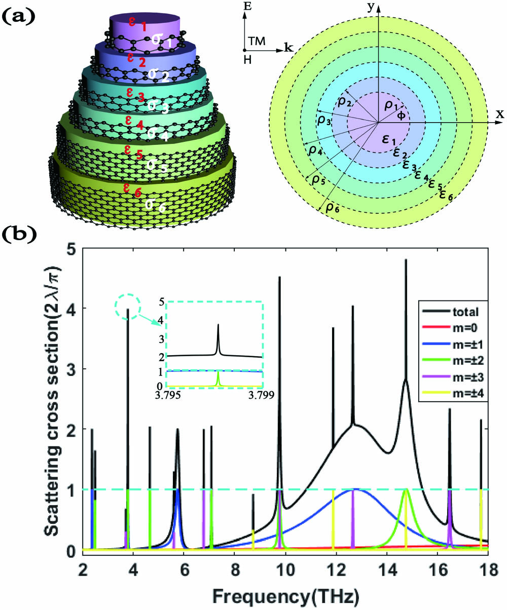
    Fig. 1. (a) Illustration of a subwavelength multilayered cylindrical structure consisting of six layers of dielectric materials, each of which is coated with a graphene shell. Three-dimensional and two-dimensional views of the structure are shown in the left and right inset, respectively. Graphene shells are represented by black dotted lines. Here, the plane wave is TM-polarized and incident from the left side of the cylinder structure. (b) The scattering spectra (normalized scattering cross section) for the same structure in (a) under the ideal lossless assumption. Both the total scattering spectrum and the partial spectra of the first five scattering terms are shown. The inset in (b) shows the details at the resonance peak circled by a dotted blue line.
    Dispersion of plasmon polaritons versus |RTM| (in logarithmic scale) under the ideal lossless assumption is shown. RTM is the reflection coefficient of the TM-polarized plane wave for the corresponding planar structure. The parameters of the corresponding planar structure are the same as those in Fig. 1(a), including the geometrical parameters d1 = 1493 nm, di = 500 nm (i = 2, 3, …, 6) and material parameters ε1 = 1.22, ε2 = 1.21, ε3 = 2.06, ε4 = 1.15, ε5 = 1.21, and ε6 = 2.3. All of the graphene shells with µc = 0.72 eV are represented by black dotted lines, the thickness of which can be negligible.
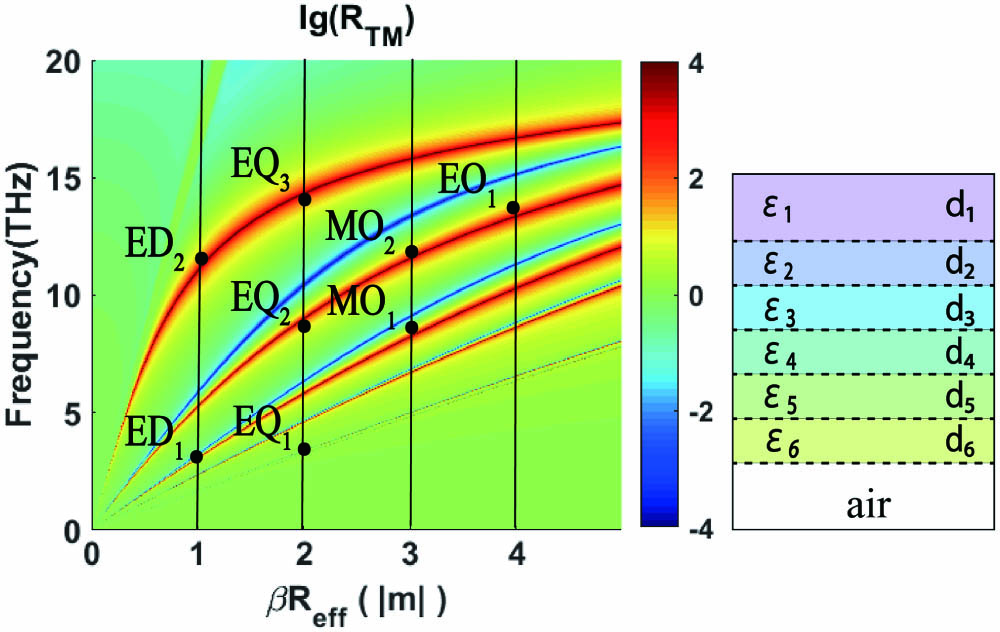
    Fig. 2. Dispersion of plasmon polaritons versus |RTM| (in logarithmic scale) under the ideal lossless assumption is shown. RTM is the reflection coefficient of the TM-polarized plane wave for the corresponding planar structure. The parameters of the corresponding planar structure are the same as those in Fig. 1(a), including the geometrical parameters d1 = 1493 nm, di = 500 nm (i = 2, 3, …, 6) and material parameters ε1 = 1.22, ε2 = 1.21, ε3 = 2.06, ε4 = 1.15, ε5 = 1.21, and ε6 = 2.3. All of the graphene shells with µc = 0.72 eV are represented by black dotted lines, the thickness of which can be negligible.
    Scattering angular distributions for the subwavelength cylinder structure in Fig. 1(a) at (a) 3.79715 THz, (c) 9.77464 THz, (e) 12.65616 THz, and (g) 14.74908 THz are shown, and the background patterns are the near fields |Hzsca| at the corresponding frequencies. The total scattering amplitudes are plotted by solid blue curves, and the ideal scattering patterns with solely overlapped (a) ED and EQ, (c) EQ and MO, (e) ED and MO, and (g) EQ and EO are plotted by red crosses. Total magnetic-field Hz distributions at the frequencies of (b) 3.79715 THz, (d) 9.77464 THz, (f) 12.65616 THz, and (h) 14.74908 THz are plotted.
    Fig. 3. Scattering angular distributions for the subwavelength cylinder structure in Fig. 1(a) at (a) 3.79715 THz, (c) 9.77464 THz, (e) 12.65616 THz, and (g) 14.74908 THz are shown, and the background patterns are the near fields |Hzsca| at the corresponding frequencies. The total scattering amplitudes are plotted by solid blue curves, and the ideal scattering patterns with solely overlapped (a) ED and EQ, (c) EQ and MO, (e) ED and MO, and (g) EQ and EO are plotted by red crosses. Total magnetic-field Hz distributions at the frequencies of (b) 3.79715 THz, (d) 9.77464 THz, (f) 12.65616 THz, and (h) 14.74908 THz are plotted.
    (a) Influence of graphene’s losses on multifrequency superscattering is shown through the total scattering spectra for different lossy cases. Except τ, other parameters are the same as those in the structure of Fig. 1(a). Influences of the thickness d1 of the innermost layer of the dielectric and chemical potential μc of all graphene shells on multifrequency superscattering in the presence of graphene’s losses are shown in (b) and (c), respectively. Except d1 in (b) or μc in (c), other parameters are the same as those in the structure of Fig. 1(a).
    Fig. 4. (a) Influence of graphene’s losses on multifrequency superscattering is shown through the total scattering spectra for different lossy cases. Except τ, other parameters are the same as those in the structure of Fig. 1(a). Influences of the thickness d1 of the innermost layer of the dielectric and chemical potential μc of all graphene shells on multifrequency superscattering in the presence of graphene’s losses are shown in (b) and (c), respectively. Except d1 in (b) or μc in (c), other parameters are the same as those in the structure of Fig. 1(a).
    Yao Qin, Jinying Xu, Yineng Liu, Huanyang Chen. Multifrequency superscattering pattern shaping[J]. Chinese Optics Letters, 2021, 19(12): 123601
    Download Citation