
Wencheng Yu, Xiaoyong Luo, Heying Qin. Experimental Study on Monitoring Cable Broken Wire Signal by FBG Sensor[J]. Laser & Optoelectronics Progress, 2023, 60(1): 0106003
- Laser & Optoelectronics Progress
- Vol. 60, Issue 1, 0106003 (2023)
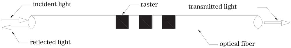
Fig. 1. Sensing principle of the FBG
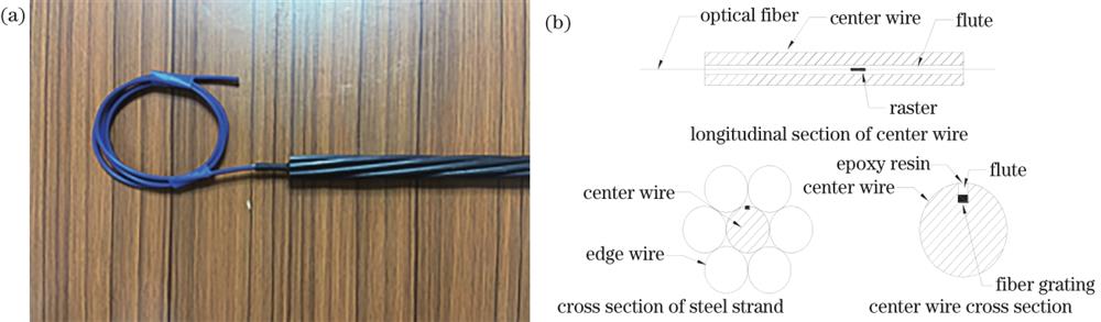
Fig. 2. Structure of self-sensing steel strand. (a) Physical drawings; (b) schematic diagram
Fig. 3. Damage location distribution of common steel strands. (a) Damage location diagram of each set of steel strand; (b) damage area of single strand of B11 steel strand 2/3
Fig. 4. Distribution of steel strands in the anchorage plate
Fig. 5. Physical drawing of the pretest tensioning machine
Fig. 6. Overall picture of steel strand after wire breaking
Fig. 7. Changes of broken wire signal of the first group of specimens in loading process. (a) B11; (b) D12; (c) D22
Fig. 8. Changes of broken wire signals of the second group of specimens in loading process. (a) B11; (b) D12; (c) D22
Fig. 9. Changes of broken wire signal of the third group of specimens in loading process. (a) B11; (b) D12; (c) D22
|
Table 1. Edge wire damage of each group of specimens
| |||||||||||||||||||||||||||||||||||
Table 2. Data of B11 specimen wire breaking
| |||||||||||||||||||||||||||||||||||
Table 3. Data of D12 specimen wire breaking
| |||||||||||||||||||||||||||||||||||
Table 4. Data of D22 specimen wire breaking

Set citation alerts for the article
Please enter your email address
© Copyright 2018-2021 | Chinese Laser Press. All Rights Reserved 沪ICP备15018463号-20