1Key Laboratory of Science and Technology on High Power Microwave Sources and Technologies,Aerospace Information Research Institute,Chinese Academy of Sciences,Beijing 101400,China
2School of Electronic,Electrical and Communication Engineering,University of Chinese Academy of Sciences,Beijing 100049,China
Jie YANG, Shou-Xi XU, Yong WANG, Xiao-Yan WANG. The effect of electron beam misalignment on confocal waveguide gyrotron traveling wave tube[J]. Journal of Infrared and Millimeter Waves, 2022, 41(4): 702
Copy Citation Text
In this paper, the effect of misaligned electron beam on the beam-wave interaction has been studied for a 0.22 THz confocal waveguide gyrotron traveling wave tube (gyro-TWT) with linear and nonlinear theory. The effect of electron beam misalignment on linear gain, critical current of absolutely instability and the exciting situation of backward wave oscillation is investigated by dispersion equation. A self-consistent nonlinear theory for confocal gyro-TWT is introduced to analyze the influence of electron beam misalignment on output power and beam-wave interaction efficiency. Meanwhile, the velocity spread is also taken into account to investigate the effect of electron beam quality on the confocal waveguide beam-wave interaction. The results show that the electron beam misalignments can cause efficiency degradation.
Terahertz(THz)science and technology is one of most prospective and essential academic fields,due to its high academic value and great application prospects,such as communications,radars,physics and materials science [1-3]. Gyro-TWT,based on convective instability,is the one of most promising THz sources,which can generate great power with broad gain bandwidth at the same time [4]. However,stability problem has always been a critical issue in the development of Gyro-TWTs. Heavily-load waveguide operated at fundamental or lower modes is one of the effective methods to control spurious oscillations [5]. Success has been achieved in gyro-TWT experiment at Ka-band with a ceramic loaded interaction structure and saturated peak power of 137 kW at 47 dB gain and 3-dB bandwidth of 1.11 GHz was obtained[6]. The demonstration of 140 kW of saturated output power,28% of efficiency and 50 dB of gain at W-band by a gyro-TWT has been achieved [7].
The size of the interaction structure decreases with increase of frequency when gyro-TWT operates at the fundamental or lower modes. In order to ensure a large enough interaction structure to hold sufficient power,the gyro-TWT needs to operate in higher-order modes. However,working in higher-order modes would inevitably lead to serious mode competition [4,8]. Therefore,a stably working at high-order mode interaction structure,which can operate at high frequency with great power,is needed. Confocal waveguide,as an all-metal structure,which can not only suppress mode competition but also avoid the use of expensive and vulnerable lossy ceramic materials,is proposed and investigated [9]. R. J. Temkin applied the confocal structure to gyrotron at the first time [10],and MIT developed the theory and has successfully implemented confocal waveguide to gyro-TWT,which has achieved the power of 30 kW and 29 dB gain at 140 GHz.
However,the manufacture of gyro-TWT has the potential to bring about the electron beam misalignment and electron optical system plays an essential role in gyro-TWT [11]. Therefore,it is necessary to study the effect of electron beam misalignment on the performance of confocal gyro-TWT. The effect of parallel shifted electron beam on beam-wave interaction in gyrotron was investigated in linear theory in[12] and a nonlinear theory of gyrotron with the eccentricity of electron beam was developed in [13]. Meanwhile,the self-consistent time-dependent theory has been modified to analyze beam–wave interaction in gyrotron resonators in the case of a misaligned electron beam [14]. For its special field distribution,the traditional analyzing methods cannot be used directly to confocal waveguide in theoretical analyses [15]. To investigate the effect of misaligned electron beam on the linear gain,instabilities,power and efficiency,we extend those methods to the linear and nonlinear theory analyses of confocal waveguide gyro-TWT. This paper is organized as follows:Section 1 shows the features of confocal waveguide. Meanwhile,the coupling factor in confocal waveguide is also analyzed with the misaligned electron beam. Section 2 presents the results of effect of electron beam misalignment on the gain,absolute instability and backward wave oscillation(BWO)by solving the dispersion equation. Section 3 demonstrates a self-consistent nonlinear theory to analyze the beam-wave interaction with the misaligned electron beam and the effect of velocity spread on the efficiency is also considered. Finally,the summery is presented in Section 4.
1 Features of confocal waveguide
Confocal waveguide consists of two identical mirrors,separated by a distance,equal to the radius of curvature of the mirrors. For a 1D Gaussian mode in the confocal waveguide,its membrane function can be presented as Ref.[4]:
ππ ,
,
,
,
whereis the coordination of electrons,and is the beam waist of wave, is the phase front radius of curvature,πis the transverse wavenumber,and is the cutoff wavenumber. We chosemode as the working mode to analyze a 0.22 THz confocal gyro-TWT.
With the local expansion of electron cyclotron orbit,we can rewriteas follows:
,
where,, is the coordination of electron cyclotron center, is the Larmor radius of electron, is the harmonic number, is the sth-order Bessel Function. The beam-wave coupling factor which characterizes the Lorentz force of the high frequency field on the electron beam can be expressed as:
.
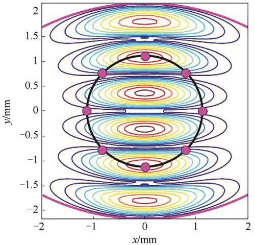
Figure 1 shows the schematic of mode and the annular electron beam which is discretized into distinct beamlets [17]. It is obvious that the value of coupling factor is related to the position of the guiding center due to the special structure of confocal waveguide. Therefore,the effect of the difference of the coupling factors at different guiding centers on the theoretical analyses must be taken into account. The optimal electron beam radius corresponding to mode can be determined as 1.12 mm in which case the beam is coupled with the second and fifth peaks along the y-axis. As shown in Fig. 2,when the harmonic number,the value of is Gaussian distribution in the x-direction()and the six peaks of mode are evident along the y-axis direction. Figure 3 presents the variation of around the annular electron beam. It is easy to find that the beam-wave interaction is much stronger in the center of the mirrors(ππ)than that near the edge of mirrors(π),which is the reason for the asymmetric mode distribution of mode. For a confocal waveguide,a simple and effective way in theoretical analyses is to take the average of coupling factor as:
.
Figure 1.Transversal electric field distribution ofmode in the confocal waveguide overlaid with the distinct beamlets of annular electron beam
where is the number of guiding centers. Figure 4 presents the cross section of cofocal waveguide with the misaligned elecreom beam and is the misalignment distance. The variation of the interaction strength of working modewith the eccentricity distance can be derived from Eq. 4. As shown in Fig. 5,the coupling factor decreases with increase of eccentricity distance. The eccentricity has an influence on the performance of confocal gyro-TWT,so we will investigate the effect of eccentricity on the beam-wave interaction based on the linear and nonlinear theories.
Figure 4.Cross section of cofocal waveguide with the misaligned electron beam
In the view of electrodynamics theory,the linear dispersion equation derived from kinetic theory can be obtained by solving and transforming the Vlasov equation. Through the similar way in Ref.[18],making a special deal with confocal waveguide field distribution,and neglecting the velocity spread and diffraction loss,the normalized linear dispersion equation for confocal waveguide can be expressed as:
,
where and are the normalized frequency and axial wavenumber,respectively;, is the light speed and , and are normalized transverse and axial velocity,respectively;,, are the cyclotron frequency,relatively mass factor and Larmor radius of electron; and are electron charge and rest mass,respectively; is the external magnetic field;is the dispersion parameter, is the direct current of electron beam,and .
2.1 Linear gain
For a determinate operating frequency,the dispersion equation is a fourth-order polynomial of . The linear growth rate can be defined by the imaginary part of forward growing wave. So the corresponding gain is described as:
.
Figure 6 displays the effect of electron beam misalignment on the linear gain. When the operating parameters take the values in Table 1,it is obvious that the linear gain decreases with the increase of electron beam misalignment. Meanwhile,it is found that when the d increases,the linear gain will also decrease.
Figure 6.Gain with different electron beam misalignment versus frequency
The absolute instability in gyrotron was discussed in detail in Ref.[20]. The threshold condition of absolute instability is the saddle point of dispersion equation
,
.
When (is the external magnetic field meets grazing condition),the critical current for absolute instability can be written as:
,
where ,
and
.
It can be concluded from the Fig. 7 that increasing the voltage can increase the critical current under the same magnetic field. According to the dispersion equation,as the voltage increases,the longitudinal velocity of the electron will increase,and the grazing point of the dispersion curve will move toward the high frequency direction. Therefore,an effective way to increase the critical current of absolute instability is to increase the voltage. It is also found that the critical current increases with the increase of the electron beam misalignment.
Figure 7.Critical current of absolute instability versus voltage
Based on the above analysis,the critical current of mode absolute instability can reach 20A,which is much higher than the operating current. Therefore,in the confocal waveguide Gyro-TWT design,the operating current usually does not depend on the critical current of absolute instability,but on the staring current of BWO. BWO is always a major factor of the stability of the Gyro-TWT. The starting current of BWO can be derived as:
π ,
.
The main backward wave oscillation mode for the fundamental mode is mode,which also has the smallest starting length of all the backward wave modes. Figure 8 illustrates the effect of electron beam misalignment on the starting current of BWO. When the operating current is 5 A and is 0 mm,the critical interaction length of mode BWO is.It is found that the critical length of mode BWO increases from 10.8 to 11.2 mm when the electron beam misalignment d increases from 0 to 0.7 mm.
Figure 9 shows the cross section of a confocal gyro-TWT interaction structure and the coordinate parameters of electron beam with misalignment. is the center of the confocal waveguide and is the center of misaligned annular electron beam; is the distance between two centers. The parameters in coordinate system can be expressed as:
,
,
,
.
Figure 9.Coordinate system for gyrating electrons with misalignment in a confocal waveguide
By neglecting the beam effects on the transverse field distribution,fields of mode
in a confocal waveguide gyro-TWT can be demonstrated as follows:
,
where is the field profile function along the axis. Substituting Eq. 11 into Maxwell equations,the equation for the evolution of the EM wave amplitude in a confocal waveguide under the excitation of a current source can be obtained as:
,
where is the total number of discrete electrons,and ,are the transverse velocity and axis velocity of the electrons,respectively. In the beam-wave interaction of gyro-TWT,the electrons are mainly modulated by EM field and external static magnetic field. Therefore,the relativistic equation of motion is expressed as follows:
,
where , is the velocity, and are given by Eq. 11,and is the external field. Through the relation,and let ,and after calculation and transformation,Eq. 13 that changes from the vector form to a series of scalar equations can be rewritten as follows:
,
,
,
,
,
.
All of the parameters are shown in Fig. 9. For a gyro-TWT,at the input end(),the initial boundary condition is
,
where is the input power. Equations 10-15 constitute a set of frequency-domain steady-state,self-consistent nonlinear theory that can be applied to arbitrary cross section. A nonlinear numerical program was developed to analyze beam-wave interaction of confocal gyro-TWT.
By setting the input power as 30 W,the nonlinear theory derived previously can be applied to investigate the beam-wave interaction in presence of misaligned electron beam. Based on the nonlinear theory,the output power is calculated and analyzed in the situation of guiding center spread in a confocal waveguide gyro-TWT. As shown Fig. 10,it is obvious that the electron beam misalignment makes output power reduced at operating frequency. Meanwhile,the length of saturated power increases with the misalignment distance,indicating that a longer interaction length is required to achieve the same power and gain. Meanwhile,the beam-wave efficiency and the length required for saturation versus electron beam misalignment distance are presented in Fig. 11. It is found that the saturation length is varied with the when it changes from 0 to 0.45 mm. In general,the saturation length increases with the increase of the misalignment distance,and the increase of length is more obvious for a larger value of misalignment distance. At the same time,the efficiency decreases with the increase of the misalignment distance. Further,the reduction in efficiency causes a reduction in power. Figure 12 presents the curves of power with different electron beam misalignment. It is clear that the power deviation is not too significant near the operating frequency but the bandwidth decreases considerably because of the decrease of efficiency.
Figure 10.Axial distributions of output power with electron beam misalignment
The design parameters of the electron optical system will affect the quality of the electron beam,which is mainly manifested in the velocity spread and the guiding center spread of electron beam. Therefore,it is necessary to investigate the effect of electron beam quality on the beam-wave interaction. It can be seen from the Fig. 13 that as the velocity spread increases,the output power gradually decreases and the saturation length increases. Because the energy exchange of electrons that are in the same guiding center peak at different positions,which will affect the efficiency of interaction and the output power will take longer interaction length to its saturated state. Taking the velocity spread and electron beam misalignment into consideration,Fig. 14 illustrates relationship between the power and frequency. It is found that the variation trend of power is similar with the same value of misalignment distancewhile the bandwidth decreases with increase of velocity spread. Meanwhile,the power decreases with the increase of velocity spread and misalignment distance. Figure 15 presents the variation of power versus the electron beam misalignment distance. The power is varied with the increase of. The power when the velocity spread is not taken into account is larger than that with velocity spread electron beam. Meanwhile,it is found that the variation of power is more notable for the electron beam without velocity spread especially when the misalignment distance is small. From Fig. 14-15,we can conclude that the quality of the electron beam,including velocity spread and guiding center spread,has a significant impact on the operation of the confocal gyro-TWT. It should be noted that we have only discussed the case where the electron beam is misaligned in the x-direction. However,due to the inhomogeneous field distribution of the confocal waveguide,the effect of the misaligned electron beam on the beam-wave interaction is more complicated when the electron beam is eccentric in the y-direction. In the future,we will pay more effort on the effect of misaligned electron beam in y-direction,which may be the topic of the next paper.
Figure 13.Axial distributions of output power with velocity spread
The theoretical analysis methods of conventional gyrotron has been extended to confocal waveguide gyro-TWT and applied to case of electron beam misalignment. The effect of misaligned electron beam on the beam-wave interaction of a 0.22 THz confocal gyro-TWT has been investigated. Because of the special structure of confocal waveguide,the coupling factor varies considerably with the guiding centers of an annular electron beam,so the averaged coupling factor was applied to study the interaction between the asymmetric confocal mode and the annular electron beam with eccentricity. Based on the linear dispersion relationship,it is found that gain decreases with the increase of misalignment distance. For instabilities,the value of critical current of mode absolute instability and the critical length of mode BWO are increased when the misalignment distance of electron beam increases. Moreover,the effect of misaligned electron beam on the efficiency is also investigated based on the self-consistent nonlinear theory of confocal gyro-TWT. The power and efficiency decrease with the increase of misalignment distance. Further,the effect of velocity spread on the beam-wave interaction is also demonstrated in the nonlinear analysis. It is found that the velocity spread can deteriorate the efficiency of beam-wave interaction and the power decreases with the increasing velocity spread. All the above results indicate that the electron beam misalignment can have a significant impact on the performance of confocal gyro-TWT.
Jie YANG, Shou-Xi XU, Yong WANG, Xiao-Yan WANG. The effect of electron beam misalignment on confocal waveguide gyrotron traveling wave tube[J]. Journal of Infrared and Millimeter Waves, 2022, 41(4): 702