• Photonics Research
  • Vol. 7, Issue 9, 1066 (2019)
Yanmeng Dai1、†, Yuquan Zhang1、†, Youpeng Xie1, Dapeng Wang1, Xianyou Wang1, Ting Lei1, Changjun Min1、2、*, and Xiaocong Yuan1、3、*
Author Affiliations
  • 1Nanophotonics Research Center, Shenzhen Key Laboratory of Micro-Scale Optical Information Technology, Shenzhen University, Shenzhen 518060, China
  • 2e-mail: cjmin@szu.edu.cn
  • 3e-mail: xcyuan@szu.edu.cn
  • show less
    DOI: 10.1364/PRJ.7.001066 Cite this Article Set citation alerts
    Yanmeng Dai, Yuquan Zhang, Youpeng Xie, Dapeng Wang, Xianyou Wang, Ting Lei, Changjun Min, Xiaocong Yuan. Multifunctional geometric phase optical element for high-efficiency full Stokes imaging polarimetry[J]. Photonics Research, 2019, 7(9): 1066 Copy Citation Text show less
    Schematic of operation principle of the GPOE for polarimetry. (a) The GPOE is designed to work as a spin sorter for high (±3) and a half-wave plate for low (±1) diffraction orders, respectively. (b) Polarization ellipses of the incident light (red) and low-order diffraction beams (blue) are mirrored with each other about the x axis. Red (blue) dashed lines indicate amplitude of field components Ev at −45° (Eu at 45°) of the incident (±1 orders) beams.
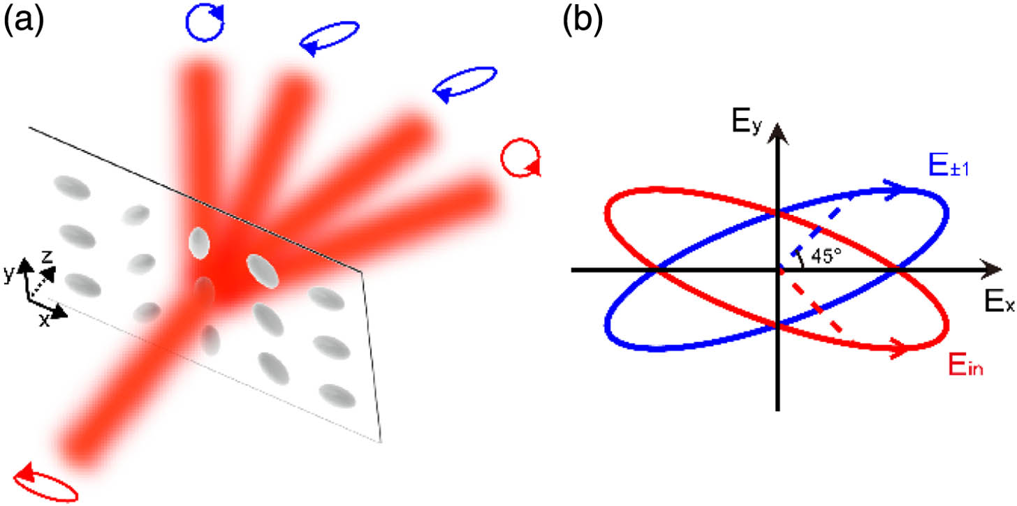
    Fig. 1. Schematic of operation principle of the GPOE for polarimetry. (a) The GPOE is designed to work as a spin sorter for high (±3) and a half-wave plate for low (±1) diffraction orders, respectively. (b) Polarization ellipses of the incident light (red) and low-order diffraction beams (blue) are mirrored with each other about the x axis. Red (blue) dashed lines indicate amplitude of field components Ev at 45° (Eu at 45°) of the incident (±1 orders) beams.
    Calculated intensities and polarization states of the diffraction orders (±1, ±3) through GPOE for the incident light with (a) LCP, (b) RCP, (c) 0°, and (d) 45° LP, respectively. In each subfigure, polarization ellipses and intensities are shown in top and middle panels, while the bottom panels show intensities through 0° and 45° polarizers indicated by gray circles and arrows.
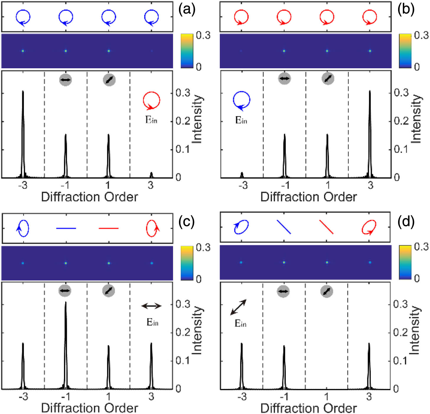
    Fig. 2. Calculated intensities and polarization states of the diffraction orders (±1, ±3) through GPOE for the incident light with (a) LCP, (b) RCP, (c) 0°, and (d) 45° LP, respectively. In each subfigure, polarization ellipses and intensities are shown in top and middle panels, while the bottom panels show intensities through 0° and 45° polarizers indicated by gray circles and arrows.
    Numerical demonstration of imaging polarimetry based on the GPOE. (a) Schematic of the optical configuration in the calculation. The scene with six areas of different polarizations is shown in left dashed box. (b) Calculated intensity map at the image plane. (c) Retrieved Stokes parameters S0−S3 (left to right panels) of the light.
    Fig. 3. Numerical demonstration of imaging polarimetry based on the GPOE. (a) Schematic of the optical configuration in the calculation. The scene with six areas of different polarizations is shown in left dashed box. (b) Calculated intensity map at the image plane. (c) Retrieved Stokes parameters S0S3 (left to right panels) of the light.
    Polarization beam splitting of the designed LC GPOE for (a) LCP, (b) RCP, (c) 0°, and (d) 45° LP incident light, respectively. Top panels: polarization ellipses; bottom panels: diffraction intensities of Ex (blue solid line) and Ey (red solid line) components. Incident polarizations are shown in the insets.
    Fig. 4. Polarization beam splitting of the designed LC GPOE for (a) LCP, (b) RCP, (c) 0°, and (d) 45° LP incident light, respectively. Top panels: polarization ellipses; bottom panels: diffraction intensities of Ex (blue solid line) and Ey (red solid line) components. Incident polarizations are shown in the insets.
    (a) Optical setup for a polarimeter based on GPOE. A polarization microscope image of the fabricated LC-GPOE is shown as the inset. (b) Experimentally detected intensity maps for the incident light of LCP, RCP, 0°, and 45° linear polarization (from top to bottom). The incident polarizations are shown in the left column.
    Fig. 5. (a) Optical setup for a polarimeter based on GPOE. A polarization microscope image of the fabricated LC-GPOE is shown as the inset. (b) Experimentally detected intensity maps for the incident light of LCP, RCP, 0°, and 45° linear polarization (from top to bottom). The incident polarizations are shown in the left column.
    Polarization imaging of a CVB beam. (a) Light intensities of each diffraction order captured by CCD. (b) Theoretical results of Stokes parameters S0−S3 of an ideal second-order CVB; arrows in the left panel indicate polarization ellipses at each position. (c) Experimental results of retrieved Stokes parameters S0−S3 for the generated CVB beam.
    Fig. 6. Polarization imaging of a CVB beam. (a) Light intensities of each diffraction order captured by CCD. (b) Theoretical results of Stokes parameters S0S3 of an ideal second-order CVB; arrows in the left panel indicate polarization ellipses at each position. (c) Experimental results of retrieved Stokes parameters S0S3 for the generated CVB beam.
    (a) Analytical (green solid line) and discretized (orange dots) phase profile of the designed GPOE. (b) Intensity (top panel) and phase (bottom panel) of the dominated diffraction orders (±1, ±3) for the analytical (green dots) and discretized (orange circled pluses) phase profile.
    Fig. 7. (a) Analytical (green solid line) and discretized (orange dots) phase profile of the designed GPOE. (b) Intensity (top panel) and phase (bottom panel) of the dominated diffraction orders (±1, ±3) for the analytical (green dots) and discretized (orange circled pluses) phase profile.
    (a) Theoretical (top panel) and experimental (bottom panel) detected intensities for linear polarization incidence of varying polarization angles. (b) Theoretical (lines) and retrieved (dots) Stokes parameters of SOP along the 30° latitude of Poincaré sphere. (c) Poincaré sphere representation of SOP obtained by rotating QWP while keeping HWP horizontally oriented.
    Fig. 8. (a) Theoretical (top panel) and experimental (bottom panel) detected intensities for linear polarization incidence of varying polarization angles. (b) Theoretical (lines) and retrieved (dots) Stokes parameters of SOP along the 30° latitude of Poincaré sphere. (c) Poincaré sphere representation of SOP obtained by rotating QWP while keeping HWP horizontally oriented.
    (a) Optical setup for characterizing the generated CVB (without GPOE) and polarization imaging (with GPOE). (b) Detected and (c) fitted theoretical intensity maps of the generated CVB.
    Fig. 9. (a) Optical setup for characterizing the generated CVB (without GPOE) and polarization imaging (with GPOE). (b) Detected and (c) fitted theoretical intensity maps of the generated CVB.
    Order−3−1+1+3
    LCP DL−0.55540.55540.55540.1374
    RCP DR0.13740.55540.5554−0.5554
    Table 1. Complex Coefficients of the Four Dominated Diffraction Orders (m=±1, ±3) for LCP, RCP Incident Light
    Yanmeng Dai, Yuquan Zhang, Youpeng Xie, Dapeng Wang, Xianyou Wang, Ting Lei, Changjun Min, Xiaocong Yuan. Multifunctional geometric phase optical element for high-efficiency full Stokes imaging polarimetry[J]. Photonics Research, 2019, 7(9): 1066
    Download Citation